Do you have a question about the Nexus 1500+ and is the answer not in the manual?
Follow standard safety precautions and wear appropriate protective gear during installation.
Consult the Installation and Operation Manual for additional safety warnings and procedures.
Refer to EIG's website for Installation Manual and software user manuals for more details.
Contact EIG Technical Support for commissioning assistance and best practices.
Install the meter into the panel cut-out using specified dimensions and mounting brackets.
Secure the meter to the panel using the four mounting brackets and screws.
Diagram for WYE or DELTA direct 3-phase, 4-wire electrical connection.
Diagram for WYE or DELTA 3-phase, 4-wire connection using Potential Transformers.
Diagram for DELTA direct 3-phase, 3-wire electrical connection.
Diagram for DELTA 3-phase, 3-wire connection using Potential Transformers.
Connect 115AC or D2 high-voltage power supply to L+, N-, and PE GND terminals.
Connect D low-voltage power supply to V(-), V(+), and PE GND terminals.
Connect PC to meter via USB; Windows 7+ installs drivers and shows Com port.
Open CommunicatorPQA software, connect, select Serial Port, Baud Rate, and Com Port.
Configure CT/PT ratios and system hookup from the Device Profile screen.
Adjust settings for communication ports (USB, Ethernet, RS485, ANSI) via Device Profile.
Set meter time via Tools>Set Device Time, using PC Time or manual entry.
Assign a unique meter designation in General Settings>Labels for reports.
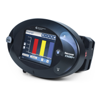
The Nexus® 1500+ Meter is a sophisticated power quality meter designed for comprehensive energy monitoring and analysis. It is intended for installation and operation by qualified personnel who are trained and experienced with high-voltage devices and follow standard safety precautions. The meter is not to be used for primary protection or in an energy-limiting capacity, but rather as secondary protection.
The Nexus® 1500+ Meter provides advanced power quality monitoring, including phasor measurement unit (PMU) capabilities. It is designed to measure and analyze various electrical parameters, offering insights into power quality, energy consumption, and system performance. The meter can be integrated with software like CommunicatorPQA™, MeterManagerPQA™, and EnergyPQA.com™ for detailed data analysis, configuration, and reporting. It supports various wiring configurations, including WYE or DELTA Direct 3 Phase (4-wire and 3-wire) and WYE or DELTA with PTs (4-wire and 3-wire), accommodating different electrical system setups. The device also features multiple communication ports, including USB Serial, RS-485, and optional Ethernet, allowing for flexible connectivity and remote management.
| Brand | Nexus |
|---|---|
| Model | 1500+ |
| Category | Measuring Instruments |
| Language | English |