Do you have a question about the Nexus 1252 and is the answer not in the manual?
Emphasizes qualified personnel, safety precautions, and avoiding contact with dangerous voltages during installation and operation.
Specifies that the meter is for secondary protection only and not for primary or energy-limiting functions.
Advises consulting the Installation and Operation Manual and Software Manual for detailed safety and operational information.
Provides links to download user manuals, software applications, and EIG's product literature.
Details how and when to contact EIG's Technical Support for assistance with product implementation and integration.
Instructions for securely mounting the Nexus® 1252 meter to a flat surface using #10 screws.
Recommends mounting in an enclosed space like a switchgear cabinet and installing a labeled disconnecting mechanism.
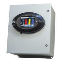
Guide for mounting the external LED display and connecting it to the meter via RS485 cable.
Details RS485 communication viability up to 4000 feet and the need for a remote power supply for longer cables.
Steps to mount output modules using brackets and connect them via RS485 cables to the meter or other modules.
Illustrates wiring configurations for 4-wire, 3-element WYE connections with various PTs and CTs.
Diagrams for 3-wire, 2-element Delta configurations with 2 PTs and 2 CTs.
Illustrates wiring for a 3-wire, 2-element Open Delta setup with 3 CTs.
Steps to connect the meter using RS485 via the CommunicatorPQA software, detailing connection parameters.
Procedure to view meter status and access the Device Profile screen for programmable settings.
Instructions for configuring CT and PT ratios, system hookup, and operational frequency range in the meter's profile.
Details default and configurable settings for serial ports, Network, and Internal Modem options.
Specific parameter settings for serial ports, including address, baud rate, data bits, parity, stop bits, delay, protocol, and mode.
Explains settings for Network Option (IP, subnet, gateway) and Internal Modem (rings, baud rate, dial out).
Important notes regarding port availability, modem settings, I/O Master configuration, and external display communication requirements.
Procedure to set the meter's internal clock, either manually or by synchronizing with the PC's time.
How to assign a unique name or designation to the meter for identification in databases and reports.
Instructions to apply changes made in the Device Profile, including meter reboot and network connection considerations.
| Brand | Nexus |
|---|---|
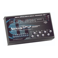
| Model | 1252 |
| Category | Measuring Instruments |
| Language | English |