EasyManua.ls Logo

Niagara JACE-9000 - User Manual

Default Icon
21 pages
Print Icon
To Next Page IconTo Next Page
Loading...
Technical Document
JACE-9000 Mounng and Wiring Guide
docs.niagara-community.comThis PDF is generated from on: February 2, 2024
Question and Answer IconNeed help?

Do you have a question about the Niagara JACE-9000 and is the answer not in the manual?

Summary

Confidentiality Notice

Trademark Notice

Copyright and Patent Notice

About this Guide

Product Documentation Overview

Describes this document's place in the Niagara technical library.

Document Content Details

Lists the products covered and prerequisites for understanding the content.

Document Change Log

Provides a record of updates and additions to this document.

Related Documentation Links

Lists other relevant documents for further information.

General Information

JACE-9000 Controller Model 15885

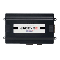
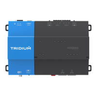
Introduces the JACE-9000 controller and its key features.

WPM-8000 Power Adapter Details

Details the wall-mount AC power adapter (WPM-8000) for the controller.

Included Controller Items

Lists the accessories supplied with the JACE-9000 controller.

Material and Tool Requirements

Specifies the materials and tools needed for installation.

Option Module and Capacity Considerations

Explains the controller's support for option modules and their combinations.

Safety Precautions and Warnings

Outlines essential safety measures for handling and installing the device.

Physical Mounting

Environmental Requirements

Specifies operating conditions, altitude, and ambient conditions for the controller.

DIN Rail Mounting Procedure

Step-by-step guide on how to mount the controller onto a DIN rail.

Tab Mounting Dimensions

Provides dimensional information for tab mounting the controller.

Wiring and Power Up

RS485 Wiring Details

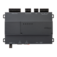
Explains how to connect RS485 ports (COM1 and COM2) to devices.

RS485 Bias Switch Settings

Describes the function and settings of the RS485 port biasing switches.

Ethernet Network Connections

Covers the setup for primary (PRI) and secondary (SEC) Ethernet ports.

Earth Ground and Power Connections

Details the proper methods for grounding and supplying power to the controller.

Power Up and Initial Checkout

Guides on applying power and verifying initial controller operation via LEDs.

Controlled Controller Shutdown

Procedure for safely shutting down the controller before removing power.

JACE-9000 Status LEDs

BEAT LED Blink Patterns

Interprets heartbeat LED patterns indicating bootup and system states.

RS485 Port LEDs

Explains the meaning of transmit (TX) and receive (RX) LEDs on RS485 ports.

STAT (Status) LED Function

Describes the green STAT LED that indicates CPU machine status.

BEAT (Heartbeat) LED Operation

Details the normal operation and blinking of the yellow heartbeat LED.

Ethernet Link and Activity LEDs

Explains the green link and yellow activity LEDs for PRI and SEC Ethernet ports.

SHUT DOWN Switch and DEBUG Port

Describes the front panel shutdown button and the debug USB-C port.

Overview

The JACE-9000 is a network controller designed for use with Niagara software, primarily by Systems Integrators. It serves as a central component in building automation and control systems, facilitating communication and data exchange between various devices. The controller is designed for indoor use and can be mounted on a DIN rail or panel-mounted.

Function Description

The JACE-9000 controller integrates with the Niagara Framework to provide monitoring and control capabilities for a wide range of building systems. It supports multiple communication protocols, including RS485 and Ethernet, allowing it to connect to and manage various field bus devices and networks. The controller's core function is to execute Niagara software applications, which can include data acquisition, scheduling, alarming, and energy management. It acts as a gateway, translating data between different protocols and enabling seamless integration of diverse equipment. The device also supports expansion modules, which can be attached to extend its communication capabilities, such as adding LonWorks or RS232 ports. The integral power supply can operate on 24Vac, 24Vdc, or a wall-mount AC power adapter. An internal microSD card is used for storing backups, which are encrypted with a system passphrase for security.

Usage Features

The JACE-9000 offers several features to facilitate its use in control systems:

  • Communication Ports: It includes two onboard RS485 ports (COM1 and COM2) for connecting to field devices, each with adjustable biasing switches (BIA, END, MID) to optimize communication in different network configurations. These ports support baud rates up to 115,200. Two RJ-45 Ethernet ports, labeled PRI (LAN1) and SEC (LAN2), provide primary and secondary network connectivity, supporting 10/100/1000 Mbit speeds. The PRI port has a factory-default IP address, while the SEC port is disabled by default but can be configured for specific applications, such as isolating network traffic.
  • Expansion Module Support: The controller can accommodate up to four DIN rail-mount option modules, expanding its communication capabilities with additional LonWorks (FTT-10) or RS232 (DB-9) ports. This modularity allows for flexible system design and adaptation to various integration requirements.
  • Status Indicators: A series of LEDs provide visual feedback on the controller's operational status. These include:
    • RS485 LEDs (TX/Yellow, RX/Green): Indicate data transmission and reception activity on the RS485 ports.
    • STAT LED (Green): Indicates CPU machine status and should remain lit when power is applied.
    • BEAT (Heartbeat) LED (Yellow): Blinks at 1 Hz during normal operation and displays specific blink patterns during bootup to indicate system state, Niagara daemon status, and station running status.
    • Ethernet LEDs (Link/Green, Activity/Yellow): Indicate Ethernet link status and network activity for both PRI and SEC ports.
  • MicroSD Card: An internal microSD card is used for storing encrypted system backups. The card is accessed by sliding open a plastic shutter located behind the mounting base.
  • Shutdown Button: A recessed SHUT DOWN pushbutton switch, accessible behind the front access door, initiates a controlled shutdown of the controller, ensuring that the station and software are put into a safe state before power removal. An associated green LED indicates the shutdown process.
  • DEBUG Port: A USB-C DEBUG port, also behind the front access door, provides serial debug communications to the controller, allowing access to the system shell menu for basic platform settings using a serial terminal program.

Maintenance Features

The JACE-9000 is designed with maintenance considerations in mind:

  • Mounting: The controller is recommended for DIN rail mounting, which ensures proper alignment of connectors between the main unit and option modules. It can also be panel-mounted. Horizontal mounting is required for maximum heat dissipation and to meet operating temperature limits.
  • Environmental Requirements: The device is built for indoor use within specific temperature and humidity ranges, and it should be installed in a static-free area, away from excessive moisture, corrosive fumes, explosive vapors, vibration, shock, or significant electrical noise.
  • Power Disconnection: A critical precaution for maintenance is to disconnect all power before installation, servicing, or attaching/detaching any option modules to prevent electrical shock or equipment damage. The use of copper conductors only and adherence to electrical codes are emphasized.
  • MicroSD Card Management: The microSD card, while typically not requiring removal, can be accessed for backup restoration. The process involves shutting down the unit, unmounting it, and carefully sliding open a shutter to access the card carrier. Static discharge precautions are necessary when handling the microSD card.
  • Troubleshooting with LEDs: The various status LEDs provide immediate visual cues for troubleshooting. For example, a constantly lit RS485 receive LED can indicate a wiring problem, and specific BEAT LED blink patterns help diagnose bootup issues. If the STAT LED does not light or the BEAT LED exhibits abnormal behavior (stays on, off, or blinks very fast), technical support should be contacted.
  • Controlled Shutdown: The SHUT DOWN button allows for a safe and controlled shutdown of the system, minimizing the risk of data loss or corruption during maintenance or power removal.
  • Accessibility: The controller's design ensures that configurable or user-serviceable items, such as switches and connectors, are accessible without removing the unit's cover. This simplifies routine checks and minor adjustments.

Niagara JACE-9000 Specifications

General IconGeneral
Ethernet Ports2
Power Supply24V AC/DC
MountingDIN Rail
Niagara Framework VersionNiagara 4
Storage8 GB Flash
Operating SystemLinux
NetworkingEthernet, Wi-Fi
Serial Ports2
USB Ports2
Operating Temperature-20°C to 60°C (-4°F to 140°F)
Dimensions138 mm x 125 mm x 60 mm (5.43 in x 4.92 in x 2.36 in)

Related product manuals