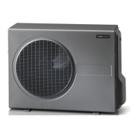
General
■
A heat pump must not be connected without the
permission of the electricity supplier and must be
connected under the supervision of a qualified elec-
trician.
■
Electrical installation and wiring must be carried out
in accordance with the stipulations in force.
■
If a miniature circuit-breaker is used this should have
motor characteristic “C” (compressor operation). For
other fuse sizes, see section "Technical Specifications"
on page 16.
■
AG-AA10 does not include an omnipolar circuit
breaker on the incoming power supply. The heat
pump’s supply cable must be connected to a circuit
breaker with a breaking gap of at least 3 mm. When
the building is equipped with an earth-fault breaker
the heat pump should be equipped with a separate
one. Incoming supply must be 230 V ~ 50 Hz via
electrical distribution units with fuses.
■
If an insulation test is to be carried out in the building,
disconnect the heat pump.
Connecting indoor and out-
door unit
Indoor unit Outdoor unit
Rated voltage
230V ~ 50Hz
A
B
C
Explanation
Power supply cableA
Communication cable
1
B
Connection cableC
1
The communication cable must always be screened. 8.5 m
screened cable supplied.
Connecting accessories
The outdoor unit is equipped for connection of a con-
densation water pipe (AG-CH10).. Connect the power
supply to AG-CH10 as illustrated:
GREY
WHITE
GREEN/YELLOW
AG-CH10
Caution
Also see the Installer manual for AG-CH10.
AG-AA10Chapter 4 | Electrical connections6
4 Electrical connections

 Loading...