EasyManua.ls Logo

Nibe AG-AA10 Series - User Manual

Nibe AG-AA10 Series
24 pages
Print Icon
To Next Page IconTo Next Page
Loading...
Installer manual
AG-AA10-30
AG-AA10-40/50
AG-AA10
Air/air heat pump
IHB GB 1516-1
331554
Question and Answer IconNeed help?

Do you have a question about the Nibe AG-AA10 Series and is the answer not in the manual?

Summary

Important Information and Safety

Safety Guidelines and Symbols

General safety rules, symbols, and marking information for the appliance.

Environmental and General Safety Precautions

Information on greenhouse gases, flammable liquids, and electrical safety during installation.

Specific Safety Procedures

Specific safety instructions for installation and repair procedures.

Pre-Installation Requirements

Essential steps and requirements before starting the heat pump installation.

Electrical Safety and Connection Requirements

Guidelines for safe and compliant electrical connections for the unit.

Delivery and Handling Procedures

Unit Transport and Assembly

Proper procedures for lifting, moving, and assembling the climate unit.

Outdoor Unit Installation Site Selection

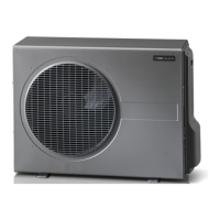
Criteria for selecting a suitable and safe installation site for the outdoor unit.

Installation Space and Clearance

Minimum space and clearance needed around the unit for operation and maintenance.

Supplied Components List

List of parts supplied with the AG-AA10-30/40/50 models.

Refrigerant Pipe Connections

General Pipe Installation Standards

Norms and directives for refrigerant pipe installation, including material and insulation.

Condensation Water Drainage

Requirements for the accessory needed to manage condensation removal.

Cooling Circuit Pipe Connection Method

Procedures for connecting the refrigerant pipes using the flare method.

Electrical Wiring and Connections

General Electrical Wiring Standards

Rules for connecting the heat pump to the power supply under electrician supervision.

Indoor;Outdoor Unit Wiring Diagram

Diagram and explanation for connecting indoor and outdoor units via cables.

Accessory Electrical Connections

How to connect the condensation water pipe accessory (AG-CH10) to the unit.

Installation Guide

Compatible Unit Combinations

Table showing compatible indoor and outdoor unit pairings.

Outdoor Unit Mounting Instructions

Detailed instructions for placing and securing the outdoor unit.

Refrigerant Pump Down Procedure

Steps for retrieving all refrigerant into the outdoor unit for movement or repair.

Service Valve Operations

Troubleshooting and Error Codes

Basic Troubleshooting Steps

Initial checks for potential issues like power and fuses.

Fault Code LED Indicators

Guide to understanding LED indicators and their corresponding causes.

Optional Accessories

Technical Specifications and Data

Physical Unit Dimensions

Diagrams showing the physical sizes of AG-AA10-30 and AG-AA10-40/50 models.

Detailed Technical Specifications

Detailed performance metrics, electrical data, and pipe sizes for all models.

Operating Range and Sound Pressure

Information on recommended working temperatures and sound pressure levels.

Other Technical Details

Enclosure class, part numbers, and notes on operating range.

Document Item Index

Overview

This document is an installer manual for the NIBE AG-AA10 series of air/air heat pumps, covering models AG-AA10-30, AG-AA10-40, and AG-AA10-50. It provides essential information for the safe and efficient installation, maintenance, and troubleshooting of these units.

Function Description

The NIBE AG-AA10 is an air/air heat pump designed to provide both cooling and heating functions for indoor environments. It operates by transferring heat between the indoor and outdoor air using a refrigerant circuit. The system consists of an outdoor unit (AG-AA10 series) and a corresponding indoor unit (AG-WT10 series, e.g., AG-WT10-4 or AG-WT10-7). The manual details the procedures for connecting the cooling circuit and electrical components, ensuring proper functionality and safety. It also covers "Pump down" procedures, which involve retrieving all refrigerant into the outdoor unit without losing the system's filling, necessary for moving the climate unit or during cooling circuit repair.

Important Technical Specifications

The AG-AA10 series heat pumps are CE marked and fulfill IPX4 protection, meaning they are protected against water drops from all angles. They contain R410A, a fluorinated greenhouse gas with a Global Warming Potential (GWP) of 2087.50.

Electrical Data:

  • Rated voltage: 230 V ~ 50 Hz for all models.
  • Fuse: 10 A for all models.
  • Max. specified power/operating current:
    • AG-AA10-30: 1550 W/6.90 A
    • AG-AA10-40: 1550 W/6.90 A
    • AG-AA10-50: 1790 W/7.80 A

Refrigerant Circuit:

  • Type of refrigerant: R410A for all models.
  • Type of compressor:
    • AG-AA10-30: Single rotary
    • AG-AA10-40: Single rotary
    • AG-AA10-50: Twin rotary
  • Volume:
    • AG-AA10-30: 0.81 kg
    • AG-AA10-40: 1.1 kg
    • AG-AA10-50: 1.3 kg

Pipe Connections:

  • Pipe connection (liquid): 6.35 mm (1/4") for all models.
  • Pipe connection (gas):
    • AG-AA10-30: 9.52 mm (3/8")
    • AG-AA10-40: 9.52 mm (3/8")
    • AG-AA10-50: 12.77 mm (1/2")
  • Min. thickness refrigerant pipe: 0.8 mm for all models.
  • Refrigerant pipes' minimum length: 1.5 m.
  • Refrigerant pipes' total length with standard filling: 7.5 m.
  • Refrigerant pipes' total length with additional filling: 15 m.
    • Additional filling for refrigerant (cooling operation): 15 g/m for 1/4"-3/8" pipes, 20 g/m for 1/4"-1/2" pipes.

Output Data (Cooling/Heating Capacity, Energy Class):

  • AG-AA10-30:
    • Cooling capacity (+35°C / 27°C): 1370/3650 W
    • Heat capacity (+7 °C / +20 °C): 930/3880 W
    • Heat capacity (-7 °C / +20 °C) max: 2650 W
    • Heat capacity (-20 °C / +20 °C) max: 2150 W
    • Pdesignc/SEER/Energy class (cooling +35 °C): 2680 W/6.1/A++
    • Pdesignh/SCOP/Energy class (heat -10 °C): 3030 W/3.82/A
  • AG-AA10-40:
    • Cooling capacity (+35°C / 27°C): 1010/4060 W
    • Heat capacity (+7 °C / +20 °C): 910/4870 W
    • Heat capacity (-7 °C / +20 °C) max: 3510 W
    • Heat capacity (-20 °C / +20 °C) max: 2980 W
    • Pdesignc/SEER/Energy class (cooling +35 °C): 3670 W/6.0/A++
    • Pdesignh/SCOP/Energy class (heat -10 °C): 4020 W/4.01/A+
  • AG-AA10-50:
    • Cooling capacity (+35°C / 27°C): 900/5650 W
    • Heat capacity (+7 °C / +20 °C): 1030/5290 W
    • Heat capacity (-7 °C / +20 °C) max: 3900 W
    • Heat capacity (-20 °C / +20 °C) max: 3040 W
    • Pdesignc/SEER/Energy class (cooling +35 °C): 5215 W/6.7/A++
    • Pdesignh/SCOP/Energy class (heat -10 °C): 4470 W/4.16/A+

Dimensions and Weight:

  • AG-AA10-30:
    • Weight: 35 kg
    • Width: 765 mm
    • Depth: 315 mm
    • Height: 544 mm
  • AG-AA10-40/50:
    • Weight: 57 kg
    • Width: 895 mm
    • Depth: 345 mm
    • Height: 630 mm

Recommended Working Range:

  • Min/max outdoor temp. during cooling: -20/50 °C
  • Min/max indoor temp. during cooling: 10/32 °C
  • Min/max outdoor temp. during heating: -20/24 °C
  • Min/max indoor temp. during heating: 0/27 °C

Miscellaneous:

  • Max. sound pressure level at 2 m (according to ISO 9614):
    • AG-AA10-30: 40 dB(A)
    • AG-AA10-40: 44 dB(A)
    • AG-AA10-50: 41 dB(A)

Usage Features

The manual primarily focuses on installation and maintenance rather than end-user features. However, it highlights the importance of correct installation for safe and efficient operation. The heat pump is designed for use in various climate conditions, with specified working ranges for both cooling and heating. It is capable of connecting to several different indoor units.

Maintenance Features

The manual provides detailed instructions for maintenance and repair procedures, emphasizing safety precautions.

  • Safety during repair: Disconnect voltage before checking or repairing electrical parts, keep hands and clothing away from moving parts, clean thoroughly after work, and ensure proper ventilation during cooling circuit tests to prevent refrigerant gas leaks.
  • Troubleshooting: A dedicated section helps identify and resolve common disturbances in comfort. It includes a table of fault codes indicated by LED lights (DL3, DL4, DL5, DL6, DL7) on the outdoor unit's terminal blocks, corresponding to issues like defective sensors (compressor, outdoor temperature, evaporator), overcurrent on compressor or fan, overheated control electronics, fault in indoor unit, communication error, or phase monitor tripped.
  • "Pump down" procedure: This is a key maintenance feature allowing the retrieval of refrigerant into the outdoor unit for relocation or repair of the cooling circuit without losing the system's filling.
  • Condensation drain: The AG-CH10 accessory is required for proper condensation removal to an external drain.
  • Pipe connections: Instructions for using the flare method, lubricating contact surfaces, and tightening connections with a torque wrench are provided to ensure a secure, leak-free cooling circuit. Leak tracing with nitrogen and soapy water is recommended before the function test.
  • Vacuuming: The manual details the process of vacuuming the indoor unit and refrigerant pipe using a vacuum pump connected to the outdoor unit, crucial for removing air and dampness that could negatively affect the heat pump's function.

Nibe AG-AA10 Series Specifications

General IconGeneral
BrandNibe
ModelAG-AA10 Series
CategoryWater Pump
LanguageEnglish