SYSTEM DIAGRAM
Caution
This is an outline diagram. Actual installations
must be planned according to applicable
standards.
EXPLANATION
Mixing valve controlled additional heat,
boiler
EM1
AXC moduleAA25
Boiler sensorBT52
External heating medium pumpGP10
Mixing valve, additionQN11
SMO S40AA35
External supply temperature sensorBT25
External return line sensorBT71
Miscellaneous
Non-return valveRM1
OUTLINE DIAGRAM WITH
SHUNT-CONTROLLED ADDITIONAL HEAT
-EM1
-GP10
-AA35-BT25
-RM1
-AA35-BT71
-
AA35
-EM1-AA25
-EM1-BT52
-EM1-QN11
-EM1
-EM1
ELECTRICAL CONNECTION
NOTE
Read section "Common electrical connection"
for instructions regarding electrical connection.
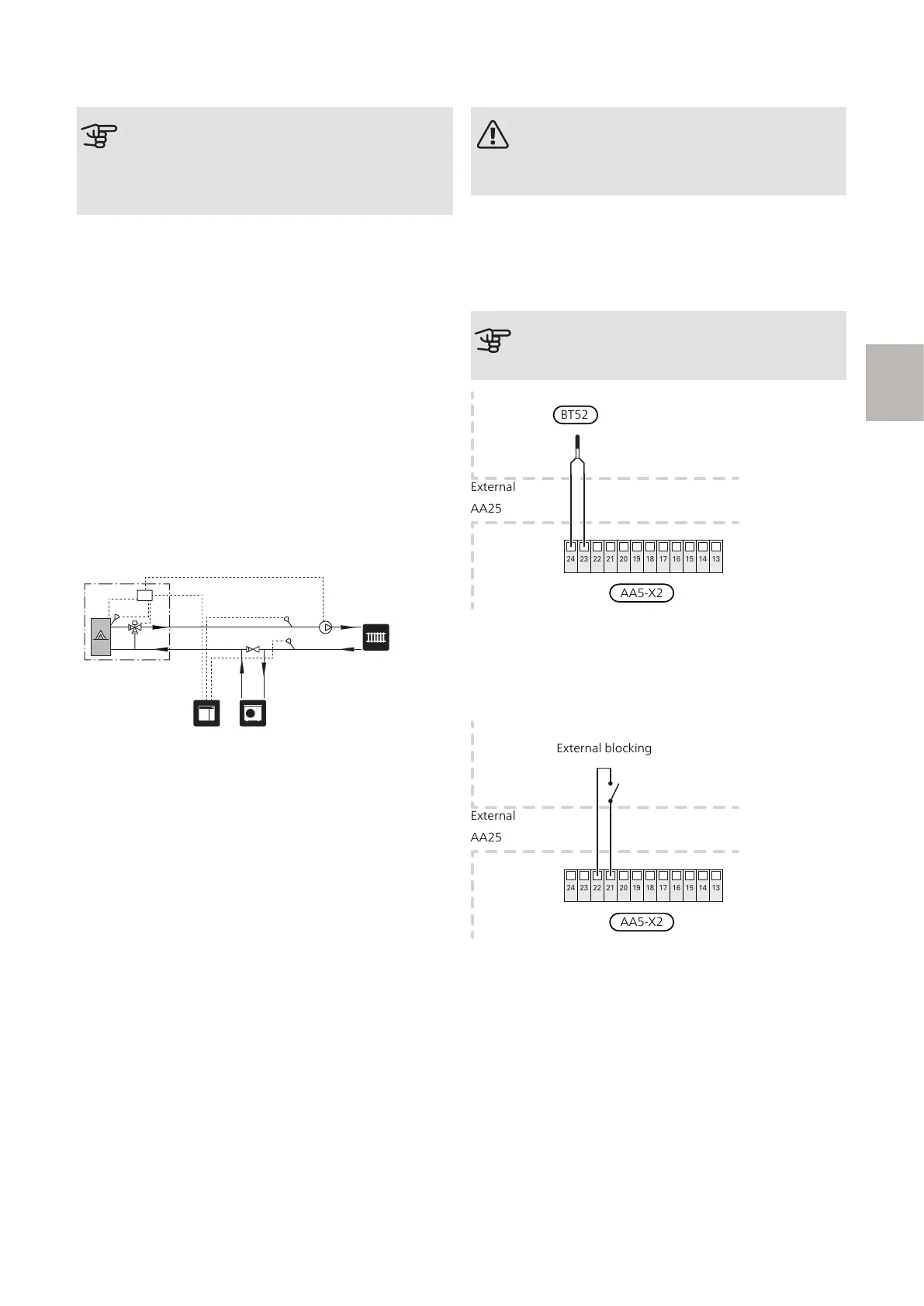
CONNECTION OF SENSORS AND EXTERNAL
BLOCKING
Boiler sensor (EM1-BT52)
Connect the sensor to AA5-X2:23-24.
Caution
Sensor cable splicing must fulfil IP54.
24 23 22 21 20 19 18 17 16 15 14 13
External blocking (optional)
A contact (NO) can be connected to AA5-X2:21-22 to
block the accessory. When the contact closes, the ac-
cessory is blocked.
24 23 22 21 20 19 18 17 16 15 14 13
AA25
External
External blocking
AA5-X2
External supply temperature sensor (AA35-BT25)
Sensor (BT25) must be connected in the main product.
See the Installer Manual for the main product.
External return line sensor (AA35-BT71)
Sensor (BT71) must be connected in the main product.
See the Installer Manual for the main product.
9AXC 30 S-series | GB
S