Caution
The relay outputs on the accessory board can
have a max load of 2A (230V) in total.
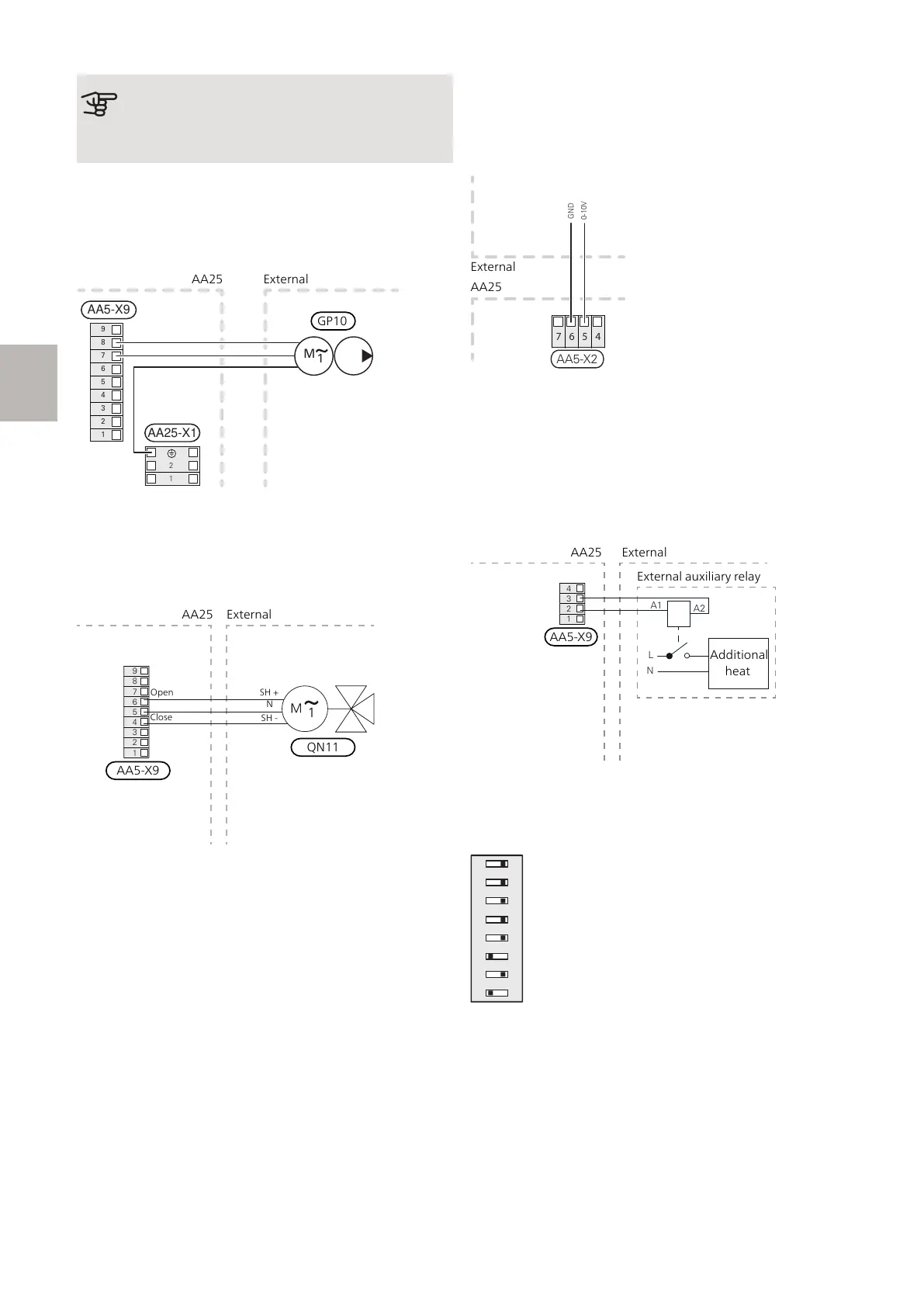
CONNECTION OF THE CIRCULATION PUMP
(EM1-GP10)
Connect the external heating medium pump (GP10) to
AA5-X9:7 (N), AA5-X9:8 (230 V) and X1:PE.
1
2
3
4
5
6
7
8
9
AA5-X9
2
1
1
M
AA25-X1
CONNECTION OF THE SHUNT VALVE
MOTOR (EM1-QN11)
Connect the shunt motor (QN11) to AA5-X9:6 (230V,
open), AA5-X9:5 (N) and AA5-X9:4 (230V, close).
AA25
External
AA5-X9
QN11
Open
SH +
N
SH -
Close
Connection of 0-10 V control of shunt motor
(EM1-QN11)
Connect a 2-core cable to AA5-X2:5 (0-10 V) and AA5-
X2:6 (GND).
At 0 V the shunt is closed and at 10 V the shunt is open.
CONNECTION OF THE AUXILIARY RELAY
FOR ADDITIONAL HEATING
Connect the auxiliary relay for switching the additional
heat on and off to AA5-X9:2 (230V) and AA5-X9:3 (N).
L
N
A1
A2
External auxil
iary relay
Additional
Heating
1
2
3
4
Additional
heat
External auxiliary relay
AA5-X9
AA25 External
DIP SWITCH
The DIP switch (S2) on the accessory board (AA5) must
be set as follows.
AXC 30 S-series | GB10
S
 Loading...