8 NIBE BA-SVM 10-200
P
P
AA4
XL10
BT63
BT25
XL1
QN10
XL2
XL3
BT71
XL5
XL4
EB1
QN12
BT64
XL11
XL19 XL18
GP12
BT12
XL14
EP2
BT15
XL13
CM1
HS1
BP4
BT3
BT7
BT6
FL1
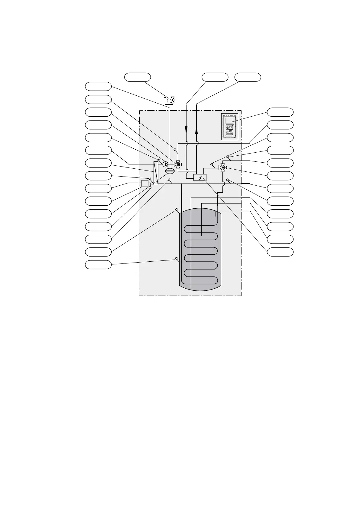
3 System description
Principle of operation
Pipe connections
XL1 Connection, heating medium, supply
XL2 Connection, heating medium, return
XL3 Connection, cold water
XL4 Connection, hot water
XL5
Connection, hot water circulation
XL10
Connection, cooling operation
XL11 Connection, safety assembly,
pressure gauge
XL13 Connection, liquid refrigerant
XL14 Connection, gas refrigerant
XL 18 Connection, return to add. heat source
XL 19 Connection, supply from add. heat source
FL1 Safety group
HVAC components
CM1 Expansion vessel, closed
QN10 Reversing valve, hot water/climate system
QN12 Reversing valve, heating system/cooling
system
Sensors etc.
BP4 Pressure sensor, high pressure
BT3 Temp. sensor, heating medium return
BT6 Temp. sensor, hot water charging
BT7 Temp. sensor, hot water heater top
BT12 Temp. sensor, condenser out
BT15 Temp. sensor, liquid line
BT25 Temp. sensor, heating medium supply
BT63 Temp. sensor, supply heating medium
behind immersion heater
BT64 Temp. sensor, cooling operation system
supply
BT71 Temp. sensor, heating medium return
EB1 Electric additional heat
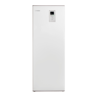
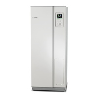
AA4 Display
Section 3 | System description
GP12 Circulation pump
EP2 Heat exchanger
HS1 Drying filter
 Loading...