Do you have a question about the Nibe ACVM 270 and is the answer not in the manual?
General information for homeowners, including system overview and safety.
Details to be completed by the installation engineer for system installation.
Instructions for the proper disposal of packaging and used products.
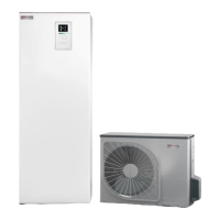
Overview of the NIBE SPLIT ACVM 270 heat pump system and its features.
Overview of the NIBE SPLIT ACVM 270 heat pump system.
Key features and benefits of the NIBE SPLIT ACVM 270 system.
Explanation of how the heat pump system functions during heating and cooling.
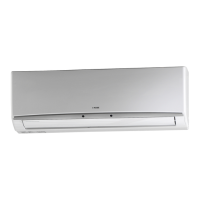
Detailed description of the indoor module's front panel controls and display.
Guidance on operating the control panel using buttons and menus.
Explanation of different menu access levels (Normal, Extended, Service).
Procedure for activating and deactivating the panel's key lock function.
Instructions for configuring heating comfort settings for the system.
Explanation of the different operating modes and their indicators.
Method for adjusting room temperature using the offset heating curve knob.
Instructions for configuring cooling comfort settings for the system.
How cooling is managed based on outdoor temperature in AutoK mode.
Instructions for configuring hot water settings for the system.
Explanation of temporary and scheduled extra hot water functions.
Routine maintenance procedures for the NIBE SPLIT ACVM 270 system.
Procedure for checking the climate system and hot water heater safety valves.
Routine checks and cleaning procedures for the outdoor module.
Advice on optimizing energy consumption and comfort settings.
Troubleshooting guide for common heating and hot water problems.
A guide to symptoms, causes, and actions for common system issues.
Information on system alarms, their meanings, and recommended actions.
Procedures for resetting or acknowledging active alarms.
Table listing display alarm texts, descriptions, and potential causes.
Steps customers can take to rectify certain alarms or when to contact an installer.
General guidance and requirements for installers setting up the system.
Guidelines for safely transporting and storing the indoor and outdoor modules.
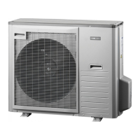
Instructions for positioning and mounting the outdoor module (AMS 10).
Detailed instructions for installing all pipe connections for the system.
Installation requirements and recommendations for connecting ACVM 270.
Diagrams showing pipe connection points and dimensions.
Instructions for making pipe connections to the climate system, including safety devices.
Instructions for connecting the hot water heater and associated valves.
Instructions for installing refrigerant pipes between outdoor and indoor modules.
Procedures for pressure testing and leak testing the system's pipe connections.
Guidelines for insulating refrigerant pipes for heat insulation and condensation prevention.
Overview of different connection options and installation requirements.
Detailed instructions for all electrical connections and wiring.
General safety and installation requirements for electrical connections.
Instructions for connecting the incoming electricity supply to the unit.
Wiring instructions for the connection between the indoor and outdoor units.
Instructions for installing and connecting the outdoor temperature sensor.
How to connect external controls for load management and tariff switching.
Connecting external sensors or timers to adjust system operation.
Procedures for system start-up, initial checks, and commissioning.
Initial steps before starting up the system, including connecting modules.
Procedure for filling the climate system with water and checking pressure.
Specific start-up steps for the ACVM 270 when the outdoor unit is not connected.
Requirement for a professional inspection before commissioning the heating installation.
A checklist of pre-commissioning checks for various system components.
Explanation of the display screen elements and operating symbols.
Description of Normal, Extended, and Service menu types.
How to navigate menus and change parameters using the control buttons.
Step-by-step guide for accessing and modifying parameter values.
Overview of the menu structure and available settings.
Access to advanced service menus for system configuration and diagnostics.
Overview of the main menu categories for system settings.
Settings related to hot water temperature and charging periods.
Settings for supply temperature for the climate system.
Settings for supply temperature for a second climate system.
Settings related to outdoor temperature readings and averages.
Readings regarding the status and operation of the outdoor unit.
Settings for room temperature control, including compensation and sensor type.
Settings for date, time, and scheduling temperature adjustments.
Settings for display, language, operating modes, and current limiter.
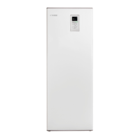
Diagrams showing the physical location of components within the indoor unit.
Diagrams showing the physical location of components within the outdoor unit.
Information on temperature sensors, their placement, and resistance values.
Physical dimensions of the indoor and outdoor modules.
Physical dimensions of the indoor module.
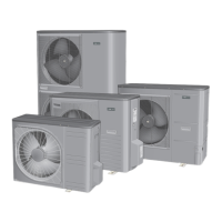
Physical dimensions of the outdoor modules (AMS 10-8).
Detailed technical data and performance specifications for the system.
Information on the energy efficiency ratings and consumption data of the system.
List and description of available accessories for the system.
Room sensor for temperature control.
Auxiliary relay for control functions.
Relay box for solar power control.
Reversing valve for cooling and heating systems.
Extra mixing valve group.
Buffer vessel or operating tank.
Cable kit for ESV 22 or VCC 22.
Insulated refrigerant pipe kit of 12 meters length.
Mounting accessory for the outdoor unit.
Mounting accessory for the outdoor unit.
Condensation water pipes in various lengths.
Important safety warnings and guidelines for installation and operation.
General warnings about installation, operation, and unqualified personnel.
Specific instructions for careful handling during electrical installation and operation.
Prohibits installation in areas with combustible gas, corrosive substances, or moisture.
| Brand | Nibe |
|---|---|
| Model | ACVM 270 |
| Category | Air Conditioner |
| Language | English |