Electrical installation
General
ACVM 270 must be installed via a circuit breaker with a
minimum breaking gap of 3mm.
Other electrical equipment, except the outdoor sensors,
current sensors and outdoor module AMS 10 is already
connected at the factory.
■
Disconnect the indoor module ACVM 270 and outdoor
module AMS 10 before insulation testing the house
wiring.
■
For fuse ratings, see technical data, “Fuse protection”.
■
If the building is equipped with an earth-fault breaker,
ACVM 270 should be equipped with a separate one.
■
Connection must not be carried out without the permis-
sion of the electricity supplier and under the supervision
of a qualified electrician.
■
5x2.5 mm
2
cable must be used for the connection
between ACVM 270 and AMS 10.
■
Cables must be routed so that they are not damaged by
metal edges or trapped by panels.
■
AMS 10 is equipped with a single phase compressor.
This means that phase L3 is loaded with up to 15 A dur-
ing compressor operation.
NOTE
Electrical installation and service must be carried out
under the supervision of a qualified electrician. Elec-
trical installation and wiring must be carried out in
accordance with the stipulations in force.
NOTE
The switch (SF1) must not be moved to “1” or “ ”
until the boiler has been filled with water. The circu-
lation pump and immersion heater may be damaged.
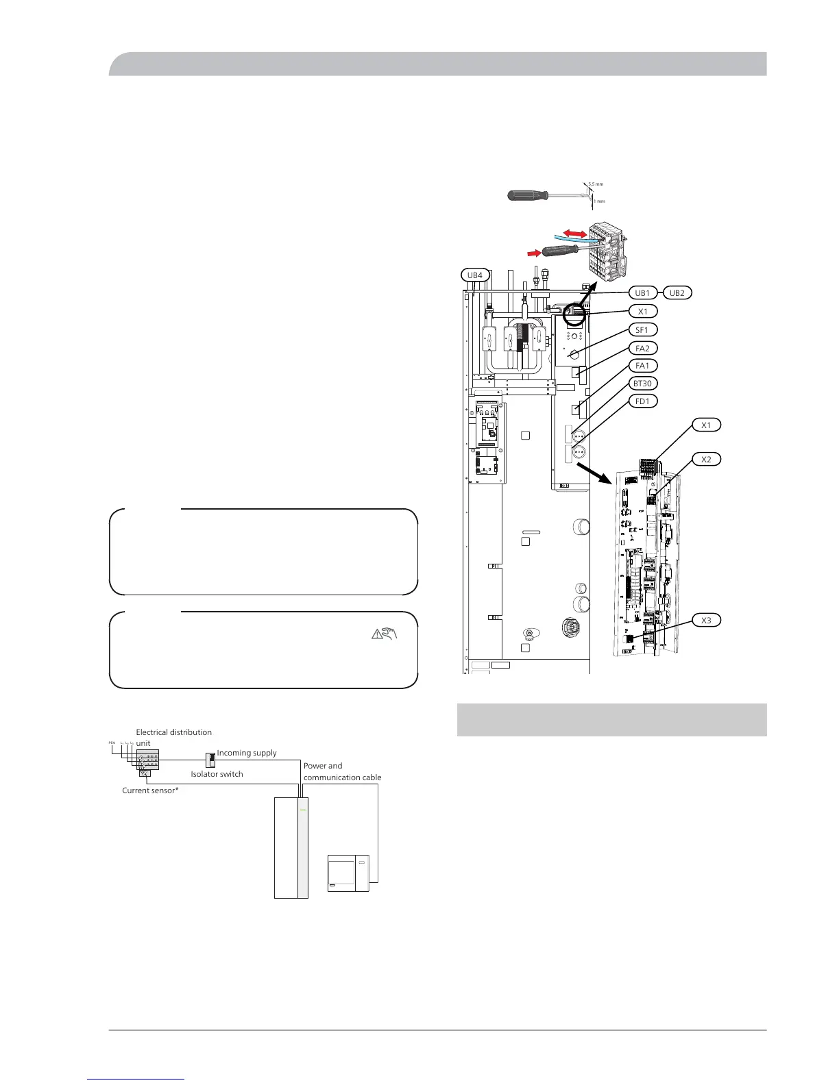
Principle diagram, electrical installation
Explanation
Scale length of
conductor (mm)
TypeDesigna-
tion
-Cable glandUB1,2,4
18Terminal block, incoming
mains supply
X1
9Terminal block, outgoing
supply and communication
X2
9Terminal block, external addi-
tion
X3
-SwitchSF1
-Miniature circuit breaker,
control system
FA1
-Miniature circuit breaker,
outdoor unit
FA2
-Thermostat, standby modeBT30
-Temperature limiterFD1
31NIBE™ SPLIT ACVM 270
For the Installer
Electrical installation