Pipe installation
General
Pipe installation must be carried out in accordance with
current norms and directives. ACVM 270 can work at a
temperature up to 65 C. For best savings, we recommend
that the climate system be dimensioned for max 55 C.
ACVM 270 is not equipped with shut-off valves. These
must be installed outside the indoor module to facilitate
any future servicing.
ACVM 270 can be connected to the radiator system, floor
heating system and/or fan convectors.
Install the supplied safety valve and manometer.
Caution
Ensure that incoming water is clean. When using a
private well, it may be necessary to supplement with
an extra water filter.
Overflow valve
NOTE
A free flow is required for all docking options, which
means that an overflow valve must be installed.
System requirements
This is required for minimum configuration:
For correct function the volume of the climate system must
comply with the installation requirements, see page 26.
If this is not fulfilled a volume vessel needs to be installed.
(NIBE UKV).
For more options, see the docking description on page 26.
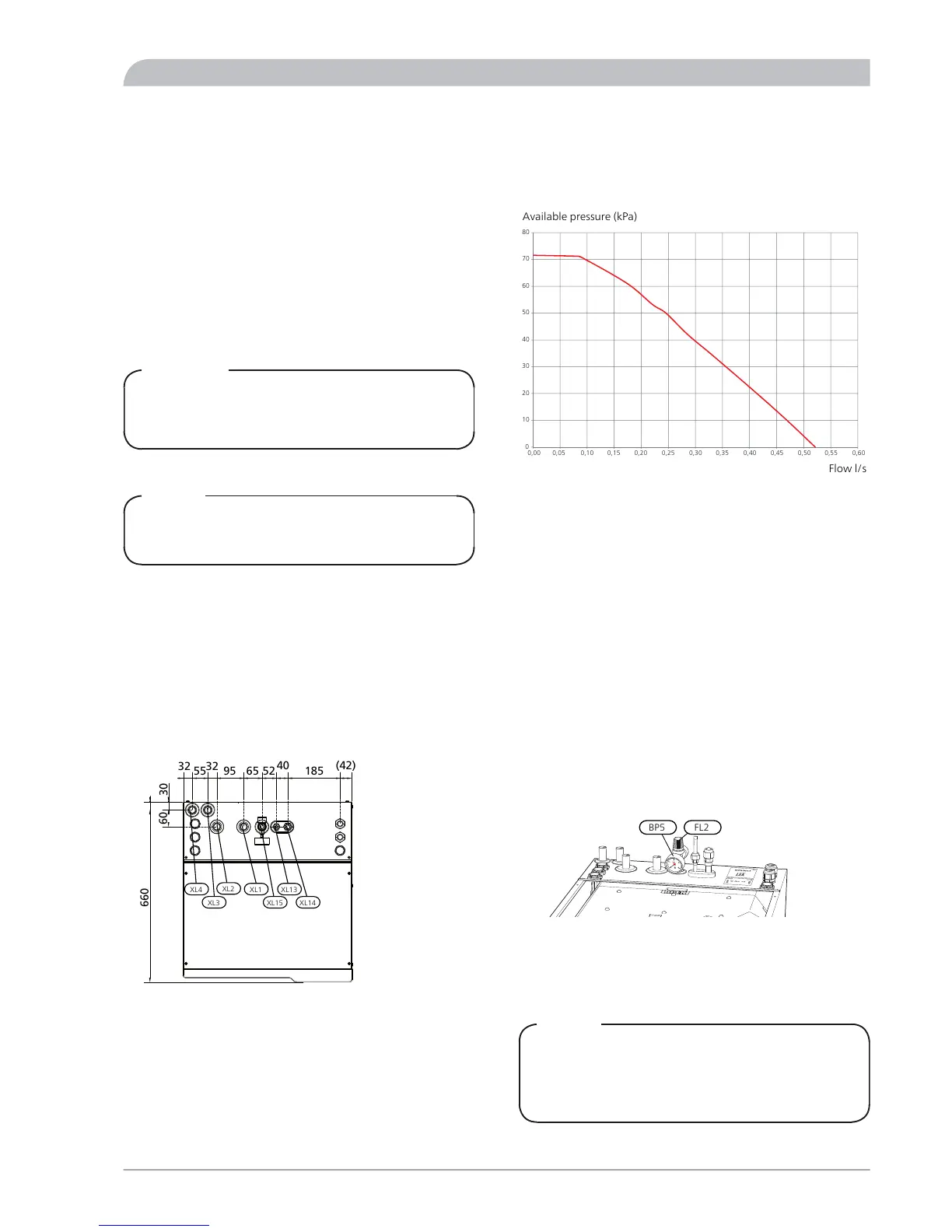
Dimensions and pipe connections
32 32
55 95 65 52 185
40 (42)
660
30
60
1760 120
350337
687
127
25-50
500 550
600
Climate system, flow Ø 22 mmXL1
Climate system, return Ø 22 mmXL2
Cold water, Ø 22 mmXL3
Hot water, Ø 22 mmXL4
Liquid line refrigerant, flare 3/8''XL13
Gas line refrigerant, flare 5/8"XL14
Connection safety valve, manometerXL15
Pump capacity diagram
0
1
0
20
30
40
50
60
70
80
Tillgängligt tryck [kPa]
Flöde [l/s]
0,00 0,05 0,10 0,15 0,20 0,25 0,30 0,35 0,40 0,45 0,50 0,55 0,60
Available pressure (kPa)
Flow l/s
The diagram shows max. performance. This can be restric-
ted in menu 2.0.
Connection of extra circulation pump
When connecting additional circulation pump GP10, to
achieve a higher flow capacity, see alternative "Underfloor
heating systems" on page 28. Respective maximum flows
must not be exceeded.
Connecting the climate system
Pipe connections for the climate system are made at the
top.
■
All required safety devices and shut-off valves must be
fitted as close to ACVM 270 as possible.
■
Install the bleed valves where necessary.
■
The safety valve (FL2) must be installed on (XL15) as illus-
trated. The overflow pipe from the safety valve must be
laid sloping along its entire length to prevent water
pockets and be frost proof.
■
When connecting to a system with thermostats on all
radiators, a relief valve must be fitted, or some of the
thermostats must be removed to ensure sufficient flow.
■
See section Dockings on page 26 for outline diagram.
NOTE
The term "Climate system" which is used in these in-
stallation and maintenance instructions regards
heating or cooling systems that are supplied with hot
or cold water from ACVM 270 for heating or cooling.
21NIBE™ SPLIT ACVM 270
For the Installer
Pipe installation
 Loading...