Do you have a question about the Nibe BA-SVM 10-200 and is the answer not in the manual?
Covers safety procedures, child usage, and interpretation of manual symbols.
Details CE marking, IP rating, and the location of the serial number.
Proper methods for disposing of packaging and used product waste.
Specifies the need for qualified inspection before system commissioning.
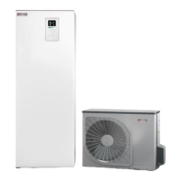
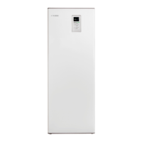
Illustrates the physical layout and labels components of the indoor unit.
Details pipe connections, HVAC parts, sensors, and electrical components.
Explains the system's fundamental working principle with a schematic.
Defines diagram symbols and presents a simplified system schematic.
Illustrates system configurations for 2-pipe and 4-pipe cooling operations.
Shows the wiring and connection for an external heat source.
Outlines the hierarchical structure of the system's menu options for navigation.
Details settings and information available in Menu 2 (Hot Water) and Menu 3 (Info).
Covers menu options for personalizing system behavior and advanced settings.
Lists service-related settings including system configuration, accessories, and country selection.
Explains Auto, Manual, and Add. heat only modes and their selectable functions.
Describes the auxiliary operation mode, its purpose, and status lamp indications.
Details how the system prevents freezing, especially in cold outdoor conditions.
Illustrates the logic for activating anti-freezing measures for the outdoor unit.
Explains emergency mode and operating with additional heat only.
Details the procedure and conditions for sensor calibration.
Covers hot water comfort levels, priority sequence, and capacity indication.
Describes settings for hot water production in different comfort modes.
Explains operation below balance point and with internal immersion heater.
Explains degree minutes calculation and adjustments to heating curves.
Details point offset adjustments and creating custom heating curves.
Explains the room sensor's role in temperature control and offset adjustments.
Describes scheduling for various system functions including hot water, heating, and holidays.
Details the 4-pipe cooling process, sensors, and related components.
Covers EB1 settings, steps, heating mode control, and defrosting conditions.
Details how the load monitor detects phase issues and protects the system.
Explains functions of AUX outputs and the role of extra heat in the charge circuit.
Describes GP12 operation, speed determination, and Delta T optimization for energy transfer.
Details settings for operating modes, waiting speeds, and highest permitted speeds.
Covers settings for DOT (°C) and dT (difference) based on preset or custom values.
Explains flow settings for GP12 and diagnostics for flow-related issues.
Details how pump speed is managed during various defrosting cycles.
Describes GP10 pump, QN10 valve, valve exercising, and floor drying function.
Details the Nibe Uplink program for remote control and its service levels.
Lists the requirements for the Uplink feature to function correctly.
Explains Smart Grid integration for optimizing energy usage based on electricity prices.
Details the effects of each Smart Grid mode on heating, hot water, and pool.
Provides guidance on using USB devices for data transfer and safe removal.
Lists standard parameters logged by the BA-SVM 10-200.
Information on managing settings, logs, and updating system software.
Details input/output connections for accessory cards.
Explains mixing valve control for additional heat and active cooling.
Lists various current menu settings for different system functions.
Explains step-controlled additional heat and hot water circulation logic.
Details accessory card functions, pool settings, and shunt group control.
Explains the connection and function of the room unit for remote control.
Details status indications for the Modbus communication module.
Outlines EB101 frequency tables for heating, hot water, and cooling modes.
Explains defrosting to water heater and inverter compressor defrosting.
Provides data tables for heating frequency settings based on outdoor temperature.
Provides data tables for hot water and pool frequency settings.
Explains the blockFreq setting that restricts compressor operation frequencies.
Lists various settings for EB101 when using On/Off control.
Explains defrosting procedures for On/Off compressors and to water heater.
Details the load monitor's role in detecting phase issues and managing electrical output.
Provides technical specifications and diagrams for the immersion heater.
Details specifications and diagrams for reversing valves.
Presents performance curves and technical data for the circulation pump GP12.
Describes the titanium anode, its dimensions, and specific product applications.
Provides resistance and voltage data for temperature sensors across a range of temperatures.
Details the functionality of main, input, and accessory electronic boards.
Describes the functions of relay boards and the components of the display unit.
Lists A-alarms, sensor faults, causes, and corrective actions.
Lists further alarms including communication faults and pressure alarms.
Lists alarms generated by the heat pump, such as inverter errors and sensor faults.
Lists alarms related to slave units and communication errors.
Details B alarms, sensor issues, condenser faults, and communication errors.
Lists alarms related to communication errors, freeze protection, and load monitoring.
Lists alarms for compressor overload, calibration issues, and external input alarms.
Provides a flowchart for diagnosing and resolving sensor fault alarm 1.
Provides a flowchart for diagnosing specific sensor fault alarms.
Provides a flowchart for sensor faults on accessory cards.
Provides a flowchart for resolving input card communication errors.
Provides a flowchart for resolving input card communication errors.
Explains how to perform relay tests and activate forced control for component checks.
Step-by-step instructions for safely removing the front cover and accessing internal components.
Guide for replacing the immersion heater, including initial preparation.
Continues the guide for replacing the immersion heater, including element removal.
Step-by-step instructions for replacing the circulation pump GP12.
Continues the guide for replacing the circulation pump GP12.
Step-by-step instructions for replacing the reversing valve QN10.
Continues the guide for replacing the reversing valve QN10.
Continues the guide for replacing the reversing valve QN10.
Detailed steps for replacing the main circuit board (AA2).
Detailed steps for replacing the input circuit board (AA3).
Detailed steps for replacing the display panel (AA4).
Detailed steps for replacing the relay board (AA7).
Detailed steps for replacing the titanium anode board (AA8).
Detailed steps for replacing the communication board (AA23).
Step-by-step guide for replacing the titanium anode.
Continues the guide for replacing the titanium anode.
Presents the main electrical circuit diagram for the system.
Details the input/output connections for the AA2 PCA base.
Illustrates the power supply and connection points for the AA2 PCA base.
Shows the input connections for the AA3 PCA module.
Illustrates the connections for the AA23 PCA accessory module.
Shows the wiring and connections for the AA7 relay board.
Illustrates the connections for the AA8 PCA Titanium Anode.
Depicts the main power supply connections and circuit protection.
Shows the physical layout and interface elements of the PCA display.
Provides overall unit dimensions and layout of pipe connections.
Lists key specifications like height, width, pressure, and temperature ratings.
Details operating currents and recommended fuse ratings for 3x400V connections.
Details operating currents and recommended fuse ratings for 1x230V connections.
Alphabetical index of topics covered in the manual with corresponding page numbers.
| Application | Residential |
|---|---|
| Refrigerant | R410A |
| Heating Capacity | 3.2 kW |
| Energy Efficiency Class (Cooling) | A++ |
| Energy Efficiency Class (Heating) | A+ |
| Weight (Indoor Unit) | 9 kg |
| Type | Split Air Conditioner |