34 NIBE BA-SVM 10-200
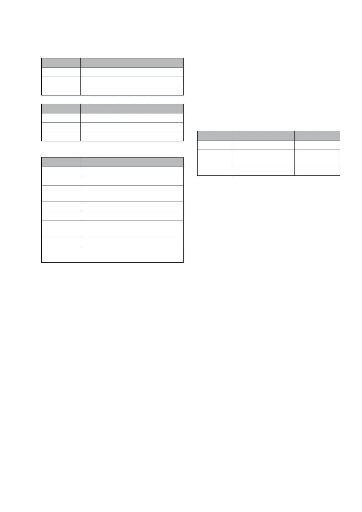
Connections, accessory card
Input Function
X2:23-24 Room sensor system 2/3/4
X2:21-22 Return line sensor 2/3/4
X2:23-24 Flow line sensor 2/3/4
Output Function
K1 Mixing valve, close
K2 Mixing valve, open
K3 External circulation pump
Communications module (MODBUS 40)
LED Indication
BATT No function.
RUN No function.
COM1 Flashes during communication with
the heat pump.
LED 4 (-) No function.
LEV No function.
COM2 No active communication between
Modbus 40 and “external control”.
SYNC No function.
VCC A steady light means that supply
voltage is OK.
Room unit (RMU 40)
• The room unit is connected to the input circuit
board (AA3-X4).
• Allows basic settings of temperature, hot water
and operating mode to be set remotely.
• If the alarm occurs the room unit displays the rel-
evant alarm number.
• The room sensor in the room unit is activated for
control of heat production via menu 1.9.4.
Current menus
Menu Name Factory setting
5.2 RMU 40 system x No
1.9.4 Control room sensor
system x
No
Factor system x -
Section 4 | Description of functions
 Loading...