33NIBE BA-SVM 10-200
Connections
Output Function
K1 -
K2 -
K3 -
K4 HWC pump GP11
Energy measurement kit (EMK 300)
The flow meter is installed on the supply line from
EB101 with the arrow in the direction of flow.
The temperature is measured using the installation’s
existing sensor.
• Activated in Menu 5.2-System settings.
Pool (POOL 40)
Address (dipswitch setting): 0110 0000
• During simultaneous heating demand the priori-
ty is determined by the settings made in menu
4.9.1.
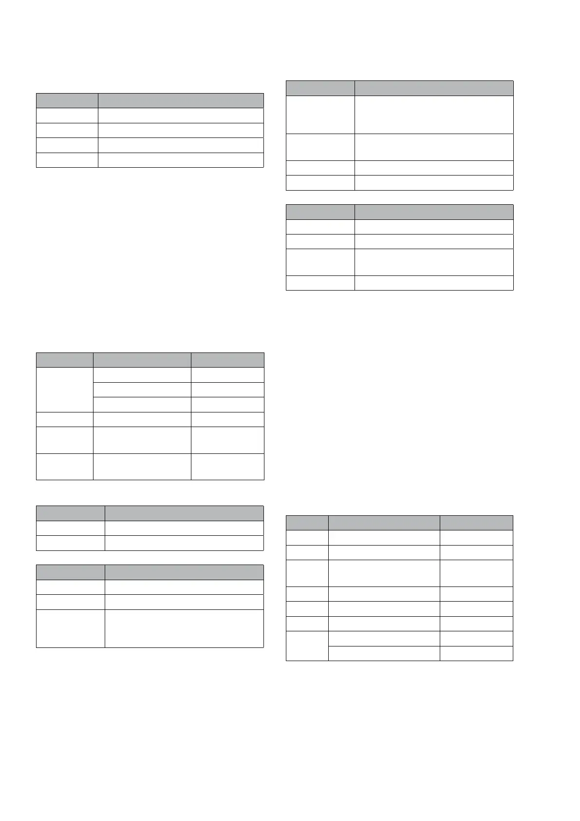
Current menus
Menu Name Factory setting
4.1.1 activated
start temp 22 °C
stop temperature 24 °C
4.9.1 op. prioritisation
5.1.11 Heating medium
pump speed
5.2 Activating/deactivat-
ing of accessories
Connections, accessory card
Input Function
AA5-X2:21-22 external blocking
AA5-X2:23-24 Pool sensor (BT51)
Output Function
AA5-X9:7-8 Circulation pump (GP9)
X1-3 Circulation pump (GP9)
AA5-X9:5 Blue cable Reversing valve motor
(QN19) as well as circulation pump
(GP14)
Output Function
AA5-X9:6 Black cable Reversing valve motor
(QN19) as well as circulation pump
(GP14)
AA5-X10:2 Brown cable Reversing valve mo-
tor (QN19).
AA5-X2:5 PWM Brown cable (GP14).
AA5-X2:6 PWM Blue cable (GP14).
Intput Function
K1 -
K2 -
K3 Pool reversing valve (QN19) as
well as (GP14).
K4 Pool pump (GP9)
Extra shunt group (ECS 40/41)
Address, climate system 2 (inst. dipswitch): 0100 0000
Address, climate system 3 (inst. dipswitch): 1100 0000
Address, climate system 4 (inst. dipswitch): 0010 0000
When heating is permitted, the shunt is controlled
to the calculated flow temperature and when cooling
is permitted the shunt is controlled to the minimum
flow temperature, in relation to supply temperature
sensor 2/3/4.
The shunt valve controls the number of whole sec-
onds as the differential (calculated flow temperature
2/3/4 – supply temperature sensor 2/3/4) * shunt
valve amplification. The mixing valves open for even
numbers and close for odd numbers. The mixing
valves are stationary during the waiting period 2/3/4.
Menu Name Factory setting
1. 1 Parallel offset 0
1.9.1 heating curve 9
1.9.2 external adjustment
2/3/4
0
1.9.3 min. flow line temp. 15 °C
1.9.4 Room sensor No
5.1.2 Max calculated flow 60 °C
5.3.3 mixing valve amplifier 1. 0
mixing valve step delay 30 secs
Section 4 | Description of functions
 Loading...