ON to OFF. This means that a visual or acoustic signal can be connected to channel 2 to signal that
the anti-theft device is connected or disconnected.
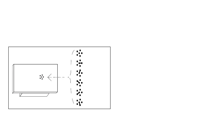
The special functions must be activated by means of a small spot of solder (Fig.7) according to the
following table:
No jumper:
all temporary channels
Jumper 1:
1 step-by-step ...2,3,4 temporary
Jumper 2:
1,2 step-by-step ...3,4 temporary
Jumper 3:
1 timer ...2,3,4 temporary
Jumper 4:
1+2 anti-theft ...3,4 temporary
Jumper 5:
all step-by-step channels
- 40 -
RICEVITORE
LATO SALDATURE
NESSUN
PONTICELLO
PONTICELLO 1
PONTICELLO 2
PONTICELLO 3
PONTICELLO 4
PONTICELLO 5
Fig. 7
No jumper
Jumper 1
Jumper 2
Jumper 3
Jumper 4
Jumper 5
RECEIVER
WELDING SIDE