EasyManua.ls Logo

Nice FLOR Series - User Manual

Nice FLOR Series
29 pages
Print Icon
To Next Page IconTo Next Page
Loading...
V. 003
Radiocomando
serie FLOR e
VERY
ricevitori
modulari
FLOXMR
FLOXM220R
Manuale di
istruzioni per
l’installazione
FLOR and
VERY Radio
control series,
modular
receivers
FLOXMR
FLOXM220R
Installation
instruction
manual
Radiocommande
série FLOR et
VERY
récepteurs
modulaires
FLOXMR
FLOXM220R
Manuel
d’instructions
pour l’installation
Funksteuerung
Serie FLOR
und VERY
Modulare
Empfänger
FLOXMR
FLOXM220R
Installation-
sanleitungen
Radiocontrol
serie FLOR y
VERY
receptores
modulares
FLOXMR
FLOXM220R
Manual de
instrucciones
para la instalación
Question and Answer IconNeed help?

Do you have a question about the Nice FLOR Series and is the answer not in the manual?

Summary

Product Description and Components

Memory Card Operation

Explains how memory cards store and manage authorized codes for receiver activation.

Installation Guide

Transmitter Installation and Checks

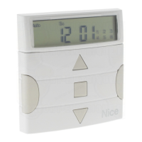
Details transmitter installation, operation verification, and battery status checks.

Transmitter Channel Selection

Explains how to modify key-channel associations on specific transmitter models.

Modular Receiver Wiring

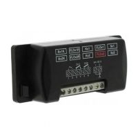
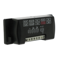
Provides instructions for wiring modular receivers, covering power and output connections.

Adjustments and Settings

Aerial Installation

Programming Procedures

Entering Code Number (Fast Way)

Details the quick method for adding transmitter codes, highlighting potential security risks.

Entering Code Number (Normal Way)

Provides the standard procedure for entering new transmitter codes via the receiver interface.

Entering Code Number (Remotely)

Explains how to add new codes using an existing authorized remote control.

Overview

This document describes the FLOR and VERY series radio control systems, including modular receivers (FLOXMR, FLOXM220R), various transmitters (FLO1R, FLO2R, FLO4R, and VR of the VERY series), memory cards (BM60, BM250, BM1000), and aerials (ABF - ABFKIT).

Function Description

The FLOR system utilizes a "Rolling Code" technique for enhanced security. Unlike traditional systems with fixed codes, the Rolling Code changes a part of the code with each transmission, following a predefined sequence. The code is masked with mathematical functions, ensuring no logical connection between consecutive codes. The receiver remains synchronized with the transmitter and only accepts the programmed code sequence. This makes it extremely difficult to copy the signal, as a "used" code will not be recognized again. The system incorporates a "code window" allowing the receiver to accept the next code plus a certain number of subsequent codes in sequence, but never a code that has already been used. If the system exits the code window, the receiver automatically re-synchronizes: the first received code is stored without activation, and the next signal synchronizes the system and activates the outputs. Automatic re-synchronization is only possible if codes are received in the established sequence.

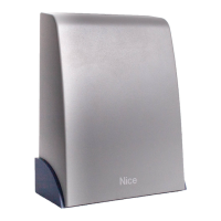
The modular receivers (FLOXMR or FLOXM220R) allow control of up to 4 channels simultaneously and can manage up to 1020 code numbers. They offer various relay output functions, including standard (MXD), timer (MXT), and step-by-step (MXP) types. Special functions can also be activated on normal MXD type modules, such as step-by-step, timer, and anti-theft functions.

Important Technical Specifications

Receivers:

  • Receiving Frequency: 433.92 MHz controlled with SAW.
  • Input Impedance: 52 ohm.
  • Sensitivity: Greater than 0.5 µV for a correctly received signal (average range 150-200 m with an ABF - ABFKIT aerial).
  • Decoding: 52-bit digital (4.5 x 10^15 combinations).
  • No. Channels: Up to 4.
  • Relay Contact (MXD, MXT, MXP): Normally open max 0.5A-50 V~.
  • Energising Time: Reception of 2 complete code numbers (200 mS).
  • De-energising Time: 300 mS from the last valid code number.
  • Working Temperature: -10°C to +55°C.
  • Size: 147 x 118 x 52 mm.

FLOXMR (Modular Receiver):

  • Power: From 10 to 28 V direct or alternate.
  • Absorption When Not Working: 15 mA.
  • Absorption of 1 Channel: 35 mA.
  • Weight: Approx. 200 g.

FLOXM220R (Modular Receiver):

  • Power: 220 Vac + 20%.
  • Absorption When Not Working: 2 VA.
  • Weight: Approx. 300 g.

Transmitters Series FLOR:

  • Carrier Frequency: 433.92 MHz controlled by SAW.
  • Radiated Power: 100µW.
  • Coding: 52-bit digital (4.5 x 10^15 total combinations).
  • Channels: 1, 2 or 4 simultaneously.
  • Power: 12 Vdc +20% - 40% with a 23A type battery.
  • Average Absorption: 25mA.
  • Working Temperature: -40°C to +85°C.
  • Size: 72 x 40 h 18.
  • Weight: 40g.
  • Approval: To I-ETS 300 220 specifications.

Transmitters Series VERY:

  • Carrier Frequency: 433.92 MHz controlled by SAW.
  • Radiated Power: 100µW.
  • Coding: 52-bit digital (4.5 x 10^15 total combinations).
  • Channels: 2 simultaneously.
  • Power: 6 Vdc with a type battery litio.
  • Average Absorption: 10mA.
  • Working Temperature: -40°C to +85°C.
  • Size: 65 x 30 h 10 mm.
  • Approval: I-ETS 300 220.

Memory Card:

  • No. Codes: 15 (BM60), 63 (BM250), 255 (BM1000).
  • Memory Type: EEPROM with serial access.
  • Memory Life: 40 years or 1 million changes.
  • Code Reading Time: 2 mS per code.
  • Size: 13x11 h9.
  • Weight: 1 g.

Accessories:

  • BUPC: Code control and programming unit.

Usage Features

Transmitter Operation:

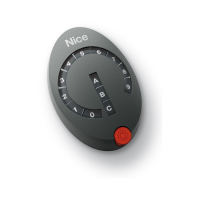
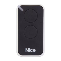
Transmitters are ready to use with pre-set code numbers. Pressing a key should cause the red LED to flash, indicating transmission. A built-in battery state control mechanism provides visual feedback: a fully charged battery results in an initial LED pulse followed immediately by the transmission signal. A partly flat battery shows an initial pulse, but transmission starts after half a second, prompting a battery change. A completely flat battery causes the LED to flash at half-second intervals without transmitting, requiring immediate battery replacement.

Channel Selection on Transmitters (FLOR1 and FLOR2):

The key-channel connection can be modified. For key 1, cut the track linking it to the 1st channel and solder one of the other pads to link it to the 2nd, 3rd, or 4th channel. The same procedure applies to the 2nd key. For VR transmitters in the VERY series, key/channel association cannot be modified.

Modular Receiver Wiring:

  • POWER (1-2): 10 to 28 Vac-dc (FLOXMR with jumper) or 220 Vac (FLOXM220R).
  • RELAY OUTPUTS (3-4, 5-6, 7-8, 9-10): Free contact of a normally open relay for 1st, 2nd, 3rd, and 4th channels respectively.
  • AERIAL (1-2): Aerial signal input.

Memory Card Usage:

Each transmitter has a unique code. The receiver activates only if a transmitter's code is on the "authorised" list on the memory card. Receivers are supplied with a BM1000 card (max 255 codes), but BM60 (max 16 codes) or BM250 (max 63 codes) can also be used. Up to 4 memory cards can be plugged in, providing a total of 1020 code numbers. Cards must be plugged in order (1st to 4th). The receiver searches codes starting from the first card. If a card is not full or missing, subsequent cards are disregarded. Memory cards must be of the same type. Upon power-on, the receiver indicates the memory card type by LED flashes (BM60: brief flash; BM250: two flashes; BM1000: three flashes).

Disabling Code Learning Function:

For maximum security, the code learning function can be disabled (locally or remotely). After entering all desired remote control codes, break the indicated track on the memory card. To re-enable, join the two pads with solder. Important: Turn off the receiver before inserting or removing a memory card.

Relay Output Contact Type:

Relay modules typically have free, normally open contacts. To obtain a normally closed contact, cut the "NO" track and join the "NC" pads with solder.

Special Functions (Activated by Solder Spot on Receiver):

  • No jumper: All temporary channels.
  • Jumper 1: 1 step-by-step, 2,3,4 temporary.
  • Jumper 2: 1,2 step-by-step, 3,4 temporary.
  • Jumper 3: 1 timer, 2,3,4 temporary.
  • Jumper 4: 1+2 anti-theft, 3,4 temporary.
  • Jumper 5: All step-by-step channels.

Programming Procedures:

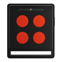
All programming operations are timed and require careful reading of instructions before execution. A small red LED indicates the procedure steps and receiver states through stable states (off/on) and flashes of two speeds (slow 1/2 second, fast 1/4 second).

  • Entering a Code Number (Fast Way): Press and hold the receiver key until the LED turns on. Transmit the code from the new transmitter until the LED turns off. Release the transmitter key. The LED will turn back on, ready for another code. This method is less secure as other transmitters in range could be memorized.
  • Entering a Code Number (Normal Way): Press the receiver key momentarily (LED on for 5 seconds). Transmit the code from the new transmitter until the LED turns off. Release the transmitter key and wait 1 second. Transmit the code again to confirm. The LED will flash 3 times upon successful entry.
  • Entering a Code Number (Remotely): Requires an already authorised remote control ("OLD") and the new remote control ("NEW"). Transmit the NEW code for at least 5 seconds. Then, slowly, transmit the OLD code 3 times. Finally, transmit the NEW code once to confirm. This operation enters the new code in all receivers within range that recognize the OLD code. Turn off unwanted receivers.
  • Deleting a Code Number: Hold the receiver key for about 3 seconds (LED turns off). Transmit the code from the transmitter until the LEDs turn off again. Release the transmitter key and wait 1 second. Transmit the code again to confirm. The LED will flash once to indicate deletion.
  • Deleting All Code Numbers: Hold the receiver key (LED turns off after 3 seconds). Release the key during the 3rd following flash. Wait about 3 seconds. Press and release the key as soon as the LED turns back on and then off. The LED will flash quickly, then 5 slow flashes, indicating reset and empty memory.
  • Checking Quantity of Stored Codes: Press the receiver key TWICE. Long flashes indicate full memory cards, short flashes indicate individual code numbers (e.g., 2 long + 10 short for BM1000 = 2x255 + 10 = 520 codes). Press the key for 1 second to stop counting.
  • Verifying/Activating/Removing 2nd Learning Disabling Function: These procedures involve pressing the receiver key and observing LED flashes. A longer 2nd flash indicates the function is active.

Programming Timer Time:

The TIMER function must be active (jumper on 3). Remove relay modules if not activating relays. Press and hold key 1 on a functioning transmitter. Within 3 seconds, press and hold the receiver key. Release the transmitter key. Release the receiver key after a time equivalent to the desired programmed time (max 2.5 hours). The receiver's normal operation is inhibited during this process.

Maintenance Features

Battery Replacement:

Transmitters indicate battery status. If the battery is partly flat, it should be changed as soon as possible. If completely flat, it must be changed immediately.

Aerial Installation:

The receiver requires an ABF or ABFKIT aerial for proper operation; without it, the range is limited to a few meters. Install the aerial as high as possible, ideally above metal or reinforced concrete structures. If the supplied cable is too short, use a 52-Ohm coaxial cable (e.g., RG58) no longer than 10 m. Connect the core to terminal 2 and the shield to terminal 1. If the earth connection is poor, connect the shield's terminal to a good earth point nearby for increased range. If an ABF or ABFKIT aerial cannot be installed, the supplied wire can be used as an aerial by laying it flat and connecting it to terminal 2.

Memory Card Handling:

Always turn off the receiver before inserting or removing a memory card to prevent damage or data corruption.

Nice FLOR Series Specifications

General IconGeneral
BrandNice
ModelFLOR Series
CategoryRemote Control
LanguageEnglish

Related product manuals