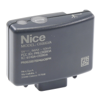
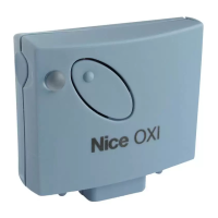
This document provides instructions and warnings for the installation and use of the Nice "Flor" series receivers, specifically the FLOXR family. These receivers are designed for use with control units in automated systems for gates, garage doors, and road barriers. Any other use is considered incorrect and forbidden, and the manufacturer disclaims liability for damage resulting from improper use.
Safety Warnings:
- All installation, connection, programming, and maintenance operations must be performed exclusively by a qualified and skilled technician.
- Do not make any modifications to the product other than those specified in this manual. Unauthorized operations can lead to hazards and malfunctions.
- Keep this manual in a safe place for future product maintenance and programming.
- Dispose of product packaging material in accordance with local waste disposal legislation.
Product Description and Intended Use:
The "Flor" series receivers handle "Flor" type radio encoding with a variable code (rolling-code) and also recognize the C-Code encoding of the Opera series for basic functions. These models feature 1 or 2 relays with clean contact output, making them compatible with any type of control unit.
Technical Specifications (for all models):
- Decoding: "FloR"
- Power Supply: 12-24 V direct or alternating (limits from 10 to 28 V).
- Power Consumption (idle): 16 mA at 24 VDC.
- Power Consumption (2 relays active): 80 mA at 24 VDC.
- Reception Frequency: 433.92 MHz.
- Sensitivity: Better than 0.5 μV.
- Number of Relays: 1 or 2, depending on the model.
- Normally Open Relay Contact: Max 0.5 A and 50 V SELV.
- Operating Temperature: From -20°C to +55°C.
- Protection Rating: IP 30.
- Dimensions and Weight: 58 mm x 86 mm x H 22 mm; 55 g.
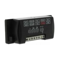
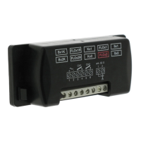
Product Installation:
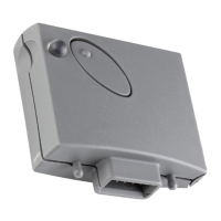
- Models with "NICE" connector: These models connect to the control system by inserting their connector into the specific one on the control unit. Important: Before connecting or removing the receiver, cut off the electricity supply to the control unit. Install the provided aerial by connecting it to the dedicated terminals on the control unit.
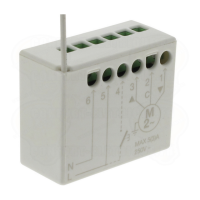
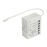
- Models with universal connection: These models feature a terminal board for universal use. They can be wall-mounted using screws (not provided) or the adhesive on the bottom of the box. Electrical connections are made as follows:
- 1-2: Power supply (12/24 V direct or alternating).
- 3-4: 1st Relay output (clean contact of a normally open relay).
- 5-6: 2nd Relay output (clean contact of a normally open relay, only on 2-channel receivers).
- 1-2: Aerial signal input.
Installing an External Aerial:
If the provided aerial is in an unfavorable position and the radio signal is weak, it is recommended to improve reception by installing an external aerial (mod. ABF or ABFKIT). The new aerial should be positioned as high as possible and away from any metallic or reinforced concrete structures. If necessary, use a coaxial cable with an impedance of 50 ohm (e.g., RG58 low-loss cable). Important: To reduce signal dispersion, use the shortest possible cable (not exceeding 10 m).
- Aerial connection (universal connection models): Connect the aerial cable to terminal 1 (sheath) and terminal 2 (core).
- Aerial connection (Nice connector models): Connect the aerial cable to the purpose-provided terminals on the control unit.
Relay Selection on Channels (for all models):
Each receiver recognizes all 4 keys on the transmitter. This is achieved by associating the output relays with the desired key using an electric jumper inserted in the provided connectors (refer to Table 1 in the manual for jumper configurations).
The outputs are operated by "NO" (normally open) type contacts. To achieve "NC" (normally closed) contacts:
- Disconnect the electrical power supply to the receiver.
- Carefully remove the board and turn it over so the welding side faces you.
- On the welding side, cut the section of line at point "X" and join the spots at points "Y" with a drop of tin.
Note: These changes can be made on one or both relays.
Selecting the Channel on the Transmitter (Flor series transmitters):
The association of the transmitter key with the receiver channel can be modified:
- For key 1: Cut the track associating key 1 with channel 1 and connect one of the other spots on the right with a drop of tin to associate it with channel 2, 3, or 4.
- For key 2: Proceed as shown in Fig. 4b of the manual.
Programming:
Programming requires the use of key P1 and LED L1 on the receiver. LED L1 indicates the status of the ongoing activity through specific flashes. Refer to Table 2 in the manual for the meaning of these indications. BUPC and OBox programmers can also be used for programming.
Signals Emitted by LED L1 on the Receiver (Table 2):
- Slow 1/2 second flash:
- 1 flash: Code received is not authorized.
- 2 flashes: Recognition time over without success.
- 3 flashes: Recognition successfully completed (code authorized).
- 4 flashes: Code is already in the list.
- 5 flashes: List is empty (no code).
- 6 flashes: List is full (no room for more codes).
- 7 flashes: Deletion of a non-existent code requested.
- 8 flashes: Different codes received during recognition.
- 9 flashes: Password entered.
- Note: If software memory lock is activated, the 2nd flash is longer than the 1st. If deactivated, both flashes are the same.
- Fast 1/4 second flash:
- During initialisation:
- 1 flash: BM60 memory present.
- 2 flashes: BM250 memory present.
- 3 flashes: BM1000 memory present.
- 4 flashes: Memory has codes not from Flor version.
- 5 flashes: Error detected during memory reading.
- During operation:
- 1 flash: Code received is a "copy"; only "original" codes are valid.
- 3 flashes: Code not in codes window, but resynchronized.
- 4 flashes: Code not in codes window and resynchronization is locked.
- 5 flashes: Code not in codes window and resynchronization is not possible.
The receiver is fitted standard with BM250 memory (up to 63 codes). Upon power-up, LED L1 indicates the memory type used.
- Usable memories: BM60 (16 codes), BM250 (63 codes), BM1000 (255 codes).
The memory stores all transmitter codes. To ensure maximum safety and prevent accidental storage of foreign codes, the code recognition function can be locked (see "Locking the memory").
Storage of a Transmitter:
A transmitter's code can be stored in two ways:
- Rapid Mode:
- Press and hold P1 on the receiver (LED L1 turns on).
- Press any key on the transmitter until LED L1 turns off.
- Release the transmitter key (LED L1 turns back on).
- Repeat for other transmitters. Release P1 when done.
- Note: This mode is quicker but less secure as it may accidentally store signals from other transmitters.
- Standard Mode:
- Press and release P1 on the receiver (LED L1 turns on for 5 sec.).
- During these 5 sec., transmit the code until LED L1 turns off.
- Release the transmitter key and wait 1 sec.
- Press and hold any key on the transmitter until LED L1 turns off (3 flashes indicate success).
- Repeat for other transmitters.
- Note: The BM memory can be locked to prevent accidental storage of unwanted signals.
Storage of a Transmitter using the 'In the Vicinity of the Receiver' Procedure (with an already stored transmitter):
A new transmitter can be stored without direct intervention on the receiver, by operating within its reception range. This requires an existing, operational transmitter.
- Warnings:
- Perform within the receiver's reception range (10-20 m).
- Repeat for each transmitter to be stored.
- Procedure:
- On the NEW transmitter, press and hold a key for at least 5 seconds, then release.
- On the OLD transmitter, press a key three times, then release.
- On the NEW transmitter, press the same key as in step 01 once, then release.
- If this does not work, repeat the process from step 01.
Total Deletion of the Receiver Memory:
WARNING! This also deletes the software lock function and resets the "Timer" to 3 seconds.
- Press and hold P1 on the receiver (LED L1 turns off after 3 sec.).
- When LED L1 starts flashing, on the 3rd flash, release P1 and wait approx. 3 sec.
- As soon as LED L1 turns back on, press and release P1 as soon as LED L1 turns off.
- LED L1 flashes quickly, then 5 slow flashes to indicate successful deletion and empty memory. If not, repeat.
Deletion of a Single Transmitter from the Receiver Memory:
- Press and hold P1 on the receiver for approx. 3 sec. (LED L1 turns off), then release.
- Press and hold any key on the transmitter until LED L1 turns off.
- Release the transmitter key and wait 1 sec.
- Press and hold any key on the transmitter to confirm (LED L1 emits 1 flash to indicate code deleted).
- If this does not work, repeat the process from step 01.
Other Functions:
Output relay function is usually momentary: relays activate a few seconds after a key press (due to code recognition time) and deactivate 300 mS after the last valid code. Special functions can be activated using a small drop of tin (refer to Fig. 5).
Jumper Configurations (Fig. 5):
- NO JUMPER: All channels momentary.
- JUMPER 1: 1 step-step, 2, 3, 4 momentary.
- JUMPER 2: 1, 2 step-step, 3, 4 momentary.
- JUMPER 3: 1 timer, 2, 3, 4 momentary.
- JUMPER 4: 1 + 2 burglar alarm, 3, 4 momentary.
- JUMPER 5: All channels step-step.
- STEP-STEP Function:
The relay activates upon pressing a transmitter key and remains active until the key is pressed again to deactivate it.
- TIMER Function:
The relay activates upon pressing a transmitter key and remains active for a programmed duration. The countdown restarts with each key press and can be stopped early by holding the same key for at least 3 sec.
- Programming the Timer:
To program the timer, activate the TIMER function (electric jumper 3, Fig. 5). If you prefer relays not to activate during programming, temporarily remove the electric jumper for channel selection.
- Programming Steps:
- Press and hold key 1 of an operational transmitter.
- Within 3 sec., also press and hold P1 on the receiver, then release the transmitter key.
- Hold P1 for the desired time (max 2 h 30'), then release P1. The time is stored until new programming.
- Note: Normal receiver operation is inhibited during timer programming.
- BURGLAR ALARM Function:
Activate this function (Jumper 4) to combine relays 1 and 2. Pressing key 1 on the transmitter activates the "Step-step" function on relay 1 (for enabling/disabling a burglar alarm). Concurrently, relay 2 (if present) performs 1 brief activation when relay 1 switches from OFF to ON, and 2 brief activations when relay 1 switches from ON to OFF. This allows relay 2 to be connected to an optical or acoustic signal to indicate burglar alarm status.
- Note: If this function is active, relay 2 maintains its normal operation associated with key 2 of the transmitter.
- Locking the Memory:
There are two ways to lock the memory:
- Hardware Lock (less secure):
- Activating: After inserting desired transmitter codes, cut the track indicated by arrow "X" (Fig. 6).
- Deactivating: Join the two spots with a drop of tin ("Y" in Fig. 6).
- Important: Perform memory enabling/disabling operations with the receiver unpowered.
- Software Lock (more secure): Requires a previously stored transmitter to deactivate.
- Activating:
- Press and immediately release P1 on the receiver.
- Wait for LED L1 to flash twice (approx. 5 sec.). At the 2nd flash, press and release P1 when LED L1 turns off.
- LED L1 emits two flashes. If the second flash is longer than the first, memory lock is active. If flashes are same length, repeat from step 01.
- Deactivating:
- Press and immediately release P1 on the receiver (LED L1 turns on for 5 sec.).
- During these 5 sec., press any key on the stored transmitter until LED L1 turns off.
- Release the transmitter key and wait 1 sec.
- Press and hold any key on the transmitter (LED L1 emits 4 flashes, indicating code is on the list).
- During the 4th flash, press and release P1 when LED L1 turns off.
- LED L1 emits two flashes of equal length, indicating memory lock is no longer active.
- If this does not work, repeat from step 01.
- Note: A safer, more controlled "PASSWORD" memory lock can be activated using BUPC and OBox programmers.
Disposing of the Product:
This product is an integral part of an automation system and should be disposed of with it. Dismantling operations must be carried out by qualified experts at the end of its lifespan. The product contains various materials, some recyclable, others requiring specific disposal. Consult local regulations for recycling or disposal systems for this product category.
- Important: Parts of the product may contain pollutants or hazardous substances.
- The symbol of a crossed-out waste bin indicates that this product must not be disposed of as domestic waste. Dispose of it as differentiated waste according to local regulations, or return it to the retailer when purchasing a new equivalent product.
- Important: Local regulations may impose heavy sanctions for illegal disposal.