2 - English
EN
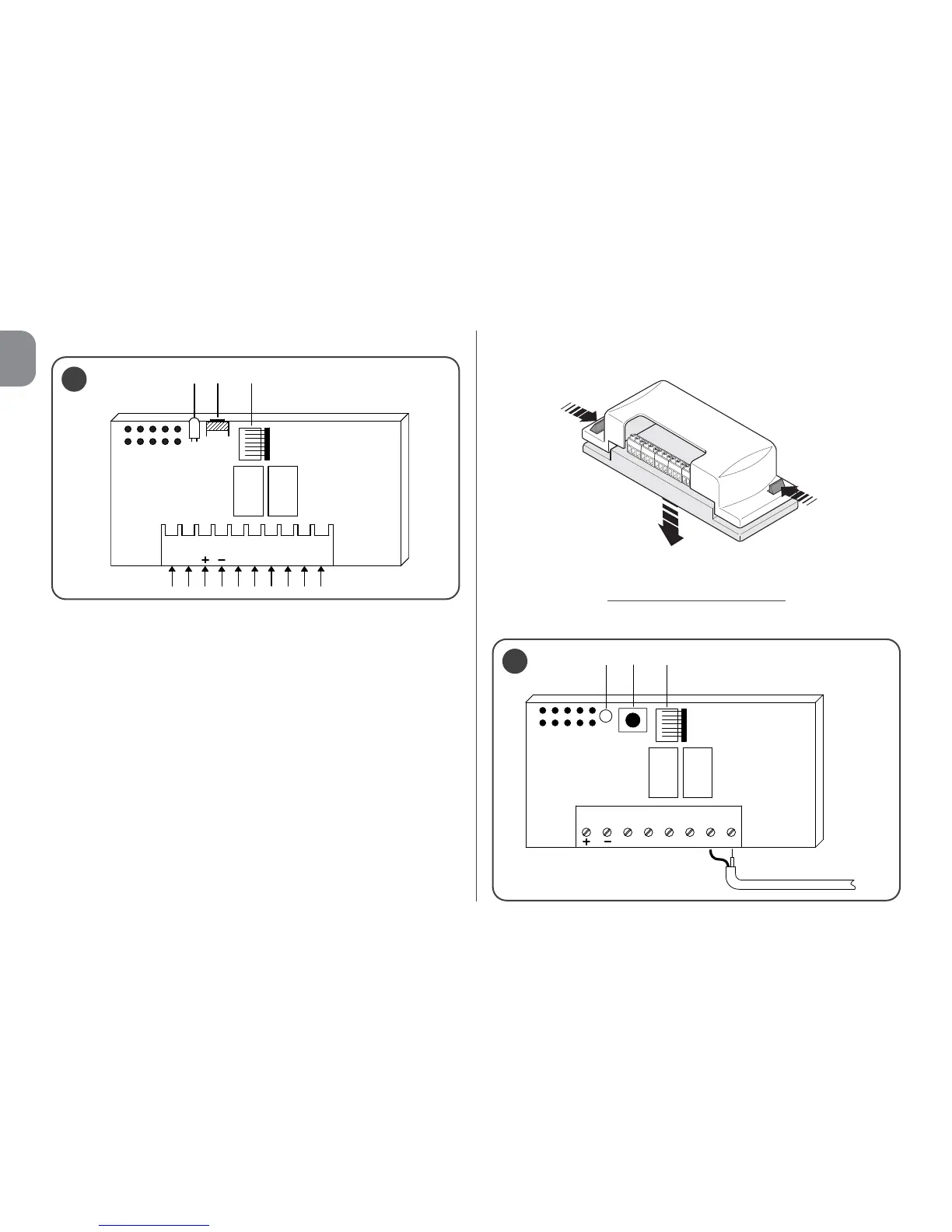
Fig. 1 illustrates the electrical connections on the connector:
A = not used
B = electricity supply
C = relay 1 output
D = relay 2 output
E = aerial
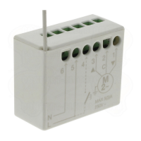
• For models with universal connection
These models with a terminal board make universal use pos-
sible; they can be wall-mounted using screws (not provided)
or using the adhesive on the bottom of the box.
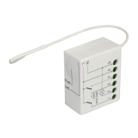
––– Electrical connections
–––
Make the connections as follows (fig. 2):
2