4
This control unit for the automation of gates and doors enables control of two gearmotors with single-phase alternating current.
The unit features a series of Dip-switches (mini switches) that enable the selection of the various functions, as well as trimmers used for mak-
ing adjustments.
The status of the inputs is signalled by LED’s located next to the inputs. An additional LED located near the microprocessor indicates whether
the internal logic is operating properly.
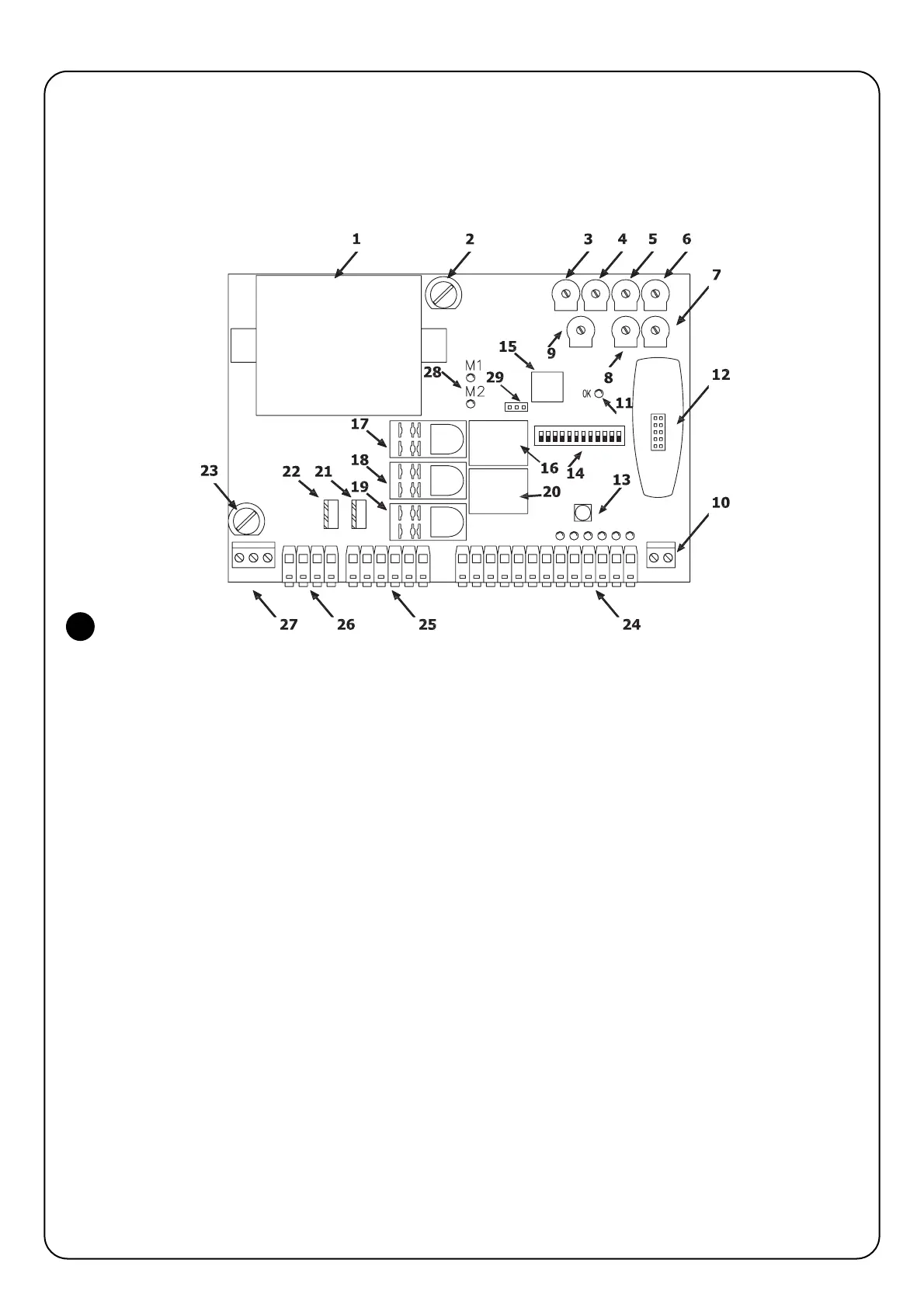
To facilitate part identification, Fig.1 below shows the most significant components.
1 Transformer
2 Low voltage fuse (500 mA F)
3 Force adjustment trimmer (F)
4 Pause Time adjustment trimmer (TP)
5 Opening Time Delay adjustment trimmer (TRA)
6 Motor 1 Working Time adjustment trimmer (TL1)
7 Motor 2 Working Time adjustment trimmer (TL2)
8 Closing Time Delay adjustment trimmer (TRC)
9 Manoeuvre balance trimmer (BAL)
10 Terminal board for aerial
11 Led OK
12 Radio slot connector
13 Step-by-step button
14 Function selection Dip-Switch
15 Microprocessor
16 Electric lock relay
17 Common motor relay
18 Courtesy light relay
19 Open / Close movement direction relay
20 Phototest relayt
21 Motor 2 Triac
22 Motor 1 Triac
23 Rapid fuse (5A 230Vac) or (6.3A 120Vac) power
24 Input / output control terminal board
25 Motor outputs terminal board
26 Flashing / C.tsy light output terminal board
27 Power supply terminal board
28 Motors ON LED
29 Jumper for selection of deceleration mode (M-RAL)
2) Product description
1

 Loading...


