SECTIN C PRO-() PRO-H() ull feature logic board mart
( () compliant)
Note The operator is shipped from the factory in the mode setting constant pressure open and close. The
operator should remain in this mode until all connections and limit switch adustments are completed.
E IIN INSTCTINS
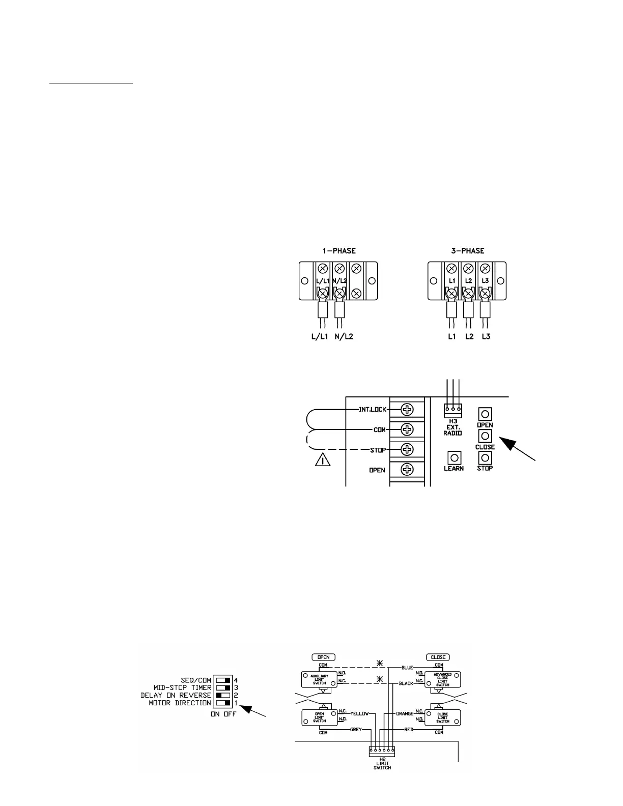
Connect primary power supply directly to the separate power terminal strip supplied using any of the - . cm
diameter holes provided on control box. o not connect power supply directly to the circuit board.
. Single phase Connect single-phase power supply to terminals and N on three-pole power terminal
strip or -phase.
. Three-phase Connect three-phase power supply to terminals , and on three-pole power terminal strip
, , , or .
N A CS S INSTCTINS
n-board pen, Close and Stop buttons are provided directly on the board for installation and troubleshooting
purposes. In order to operate unit by on-board pen, Close, Stop buttons, the factory installed umper
between the CM and ST terminals on the terminal strip must remain connected.
MT IECTIN EIICATIN
Make sure the mode of operation is selected to .
After electrical power connections are made, manually move door to mid-position. sing the on-board buttons press
the pen button for several seconds and then press the Stop button. If door did not move in correct direction or if
limit cams not moving in correct direction towards the open limit switch see below
or single-phase operators The operators leave the factory with correct motor and limit shaft direction according to
standard door installations. owever, for special fire door, through wall mounting or other special door applications, the
motor direction and limit switch direction may need to be reversed. A dipswitch ip is provided to reverse direction
of motor and limit switch direction. If motor direction is reversed, the open and close limit switches are automatically
reversed. owever, the advanced close limit switch needs to be manually changed. isconnect the wires from the
advanced closed limit switch and re-connect to the auxiliary limit switch provided.
Note Ensure that when the on-board open button is depressed and the door moves in the correct open direction that
activation of the open limit switch illuminates the EN IMIT .E. and stops the door.

 Loading...


