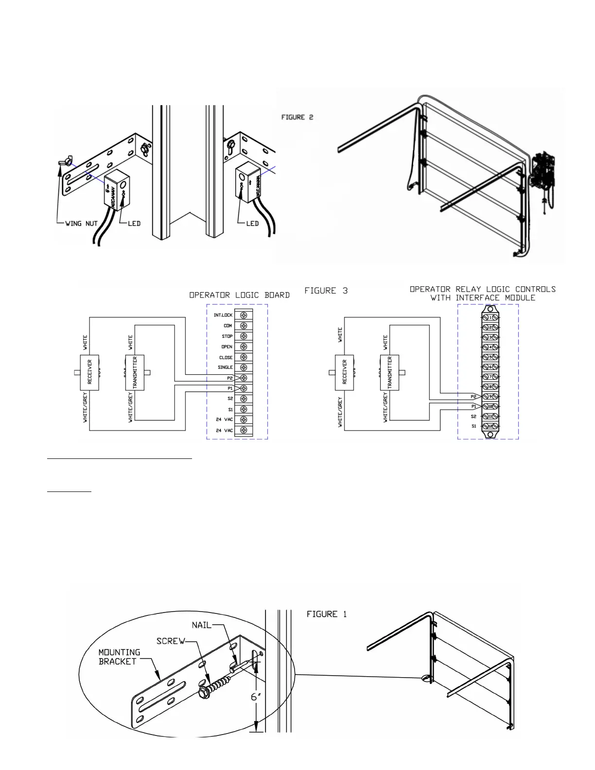
- sing the wing nuts, attach the receiver and transmitter of the photo system to the mounting brackets with
arrow pointing up. Note that the receiver and transmitter can be installed on the left side or right side of the door.
- Adust the position of the transmitter and receiver on the slot of the brackets. Secure the receiver and transmitter to
the mounting brackets as shown in figure .
- air the two white wires and the two whitegrey wires together from transmitter and receiver.
- Connect these paired wires to the and terminals on the logic board or interface module if applicable
as shown in igure .
NICE N- TCE M
ote he M photocell sstem has a maimum range of ft un isor protector optional
Installation
Note hoto beams should be mounted as close to the door track inside the door to offer maximum
entrapment protection.
all installation
. Select a
location on the wall no more than inches from the floor to install wall mounting brackets on the left
and right side of the door. oth brackets must be mounted at the same height for proper alignment.
. rill holes in the wall and attach brackets to the wall using screws and nails provided as shown in ig. .