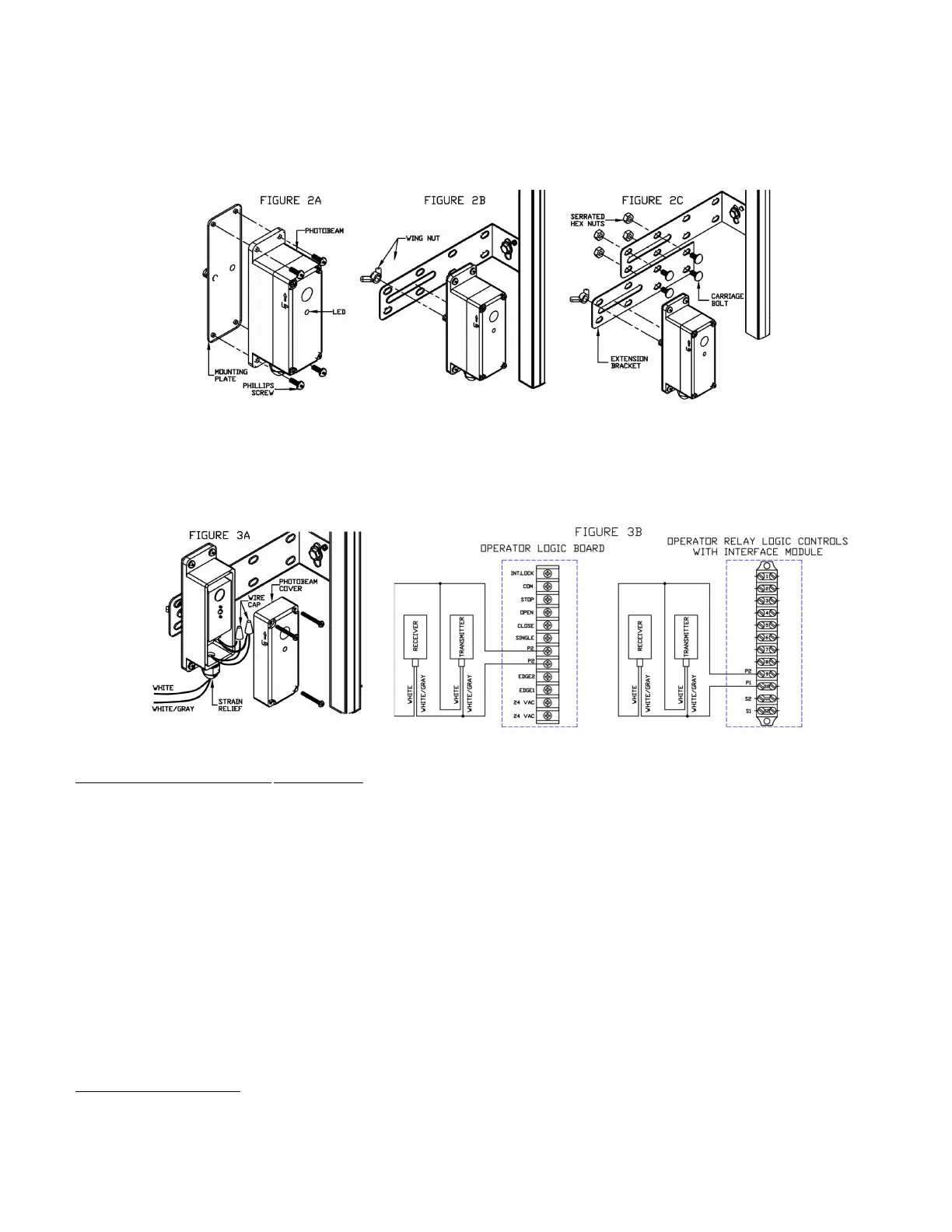
. sing the phillips head screws, attach the receiver and the transmitter to the two mounting plates ig A.
. sing the wing nuts, attach the receiver and the transmitter of the photo system to the mounting -brackets
with arrow pointing up as shown in ig . Note that the receiver and transmitter can be installed on the left
or right side of the door. or applications reuiring the photobeams to be further away from the wall, use the
extension brackets provided as shown in ig C
. Adust the position of the transmitter and receiver on the slot of the brackets and tightly secure the wing nuts
. oosen the fastening screws and remove the cover from the photobeam transmitter and receiver housings
and insert electrical wire through the strain relief ig A. air the two whitegrey wires together from
transmitter and receiver
. Connect these paired wires to the and terminals on the logic board or interface module if applicable
as shown in ig . se minimum gauge wires and secure the wires to wall or ceiling.
or Nice Nema- and Nema- photobeams Aligning the photo beams
. Turn the power on to the operator. If the transmitter and receiver are installed properly, the lights on
both the transmitter red .E.. and receiver green .E.. will be N.
. If the photo beams are not aligned properly, the receiver light green is . Adust the position of the
transmitter andor the receiver on the slot of the mounting bracket until the light on the receiver is N and
then secure to the bracket.
hoto system operation
Nice photo beams must be connected for the door to close in momentary mode unless a Nice monitored -
wire edge is connected. hen the photo system is properly installed and aligned, the infrared beam will detect any
obstruction in the path of the beam. pon detecting an obstruction, closing door will stop and reverse to full open.
The Nice operator control circuit continuously monitors the correct operation of the photo system. If the photo
beams are not connected or not functioning properly, the operator will go into fail-safe mode and closing door will
reverse to full open. In fail-safe mode door can only be closed by constant pressure on close.
To test the photo system
. pen the door to full open position.
. Close the door.
. hen door is closing, obstruct the beam. The door should stop and reverse.

 Loading...


