4 – English
EN
ASSEMBLY INSTRUCTIONS /
FIXING THE MECHANISM
According to the VDE 0113 booklet, the emergency stop
devices must also be perfectly efcient regardless of the
gearmotor operation mode. Any release of the emergency
stop device must absolutely not cause an uncontrolled or
undened restarting.
The manual emergency release is envisaged for opening and closing
the door in case of power failure, so it is to be used only in emergency
situations.
- Avoid regular use!!
Warning! Danger of injury in the case of incorrect use!
- Deactivate the main switch before using the manual emergency
release.
- The manual emergency release is to be executed only with the
motor stopped.
- The manual emergency release manoeuvre is to be executed
from a safe place.
- With a gearmotor equipped with brake (pressure), the main door
must be opened and closed with the brake open (released).
- On doors not balanced with weights, the brake is to be released
only for checking purposes with the door in the low position for
safety reasons.
- An undesirable brake release must be prevented with an adequate
check (measurement) on site.
The manual emergency release must not move the door beyond
the nal positions because in this case the main switch would
activate.
Therefore, operation of the door in electrical mode is no
longer possible.
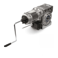
Handle-operated manual emergency release (g. 4)
- Insert the handle exerting moderate pressure, then turn it up
to when it clicks in position. In this way the control voltage is
interrupted and the door can no longer be activated electrically.
- Open and/or close the door turning the handle
- The control voltage is reset and the door can again be activated
electrically by removing the handle.
GENERAL DANGER WARNINGS AND
PREVENTIVE SAFETY
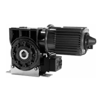
Gearmotor coupling
The gearmotor is to be coupled on the end of the winding shaft
that must be previously greased to make these tool-less assembly
operations easier. If the seat of the key on the shaft is through, the
key (tab) must be blocked to prevent accidental movement.
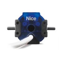
The winding shaft must not be axially secured to the gearmotor
(gearmotor side = mobile bearing). Fixing against an axial traverse of
the winding shaft is executed on the side opposite the ball bearing
using an adjustment screw or a xing ring (Fig. 1)
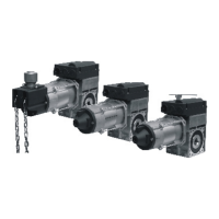
The xing brackets enable assembly both horizontally (vertical
gearmotor) and vertically (suspended motor). For different assembly
positions and for different reduction unit xing systems (different
heights of the xing brackets and accessories of the rolling shutter
systems), contact the manufacturer. The xing brackets are mounted
so that the winding shaft is horizontal.
It is important to ensure that the welded shafts are concentric and
aligned with the central axis of the main winding shaft since otherwise
the unbalances and angle defects that occur in this case could
EMERGENCY MANUAL RELEASES
The gearmotors are positive clutch startup controls with built-in
parachute device, irrespective of the rpm and position.
The parachute device follows the movement without load and wear,
and it releases in the case of failure of the mechanism.
No electrical disconnection is necessary because in the case of
failure of the mechanism, the transmission between motor, hollow
shaft and worm screw is interrupted.
After the release of the parachute device, the gearmotor is no longer
able to operate and must be replaced.
The parachute device has the following characteristics:
- protection against the breaking and wear of the toothed wheel
- it is independent from the rpm
- it is independent from the direction of rotation
- it is independent from the position
- it is independent from the vibrations
- it does not require maintenance
- it has good damping capacity in the case of intervention
WARNING:
THE BUILT-IN PARACHUTE DEVICE DOES NOT PROTECT AGAINST
THE FORCES THAT INFLUENCE THE SYSTEM FROM THE OUTSIDE
PARACHUTE DEVICE
BUILT INTO THE REDUCTION UNIT
Warnings for use
• The product is not intended for use by persons, including children,
with limited physical, sensory or mental capacities, or who lack
experience or knowledge, unless supervised or trained in the use
of the product by a person responsible for their safety.
• Any children near the automation system must be kept under
supervision to ensure that they do not play with it.
• Do not allow children to play with the xed control devices. Keep
remote control devices out of the reach of children.
The instructions shall contain at least the following information:
• the business name and full address of the manufacturer and,
where applicable, hisauthorized representative;
• model or type reference of the appliance as marked on the appli
-
ance itself, except for the serial number;
• the designation of the appliance together with its explanation in
case it is given by acombination of letters and/or numbers.
• the general description of the appliance, when needed due to the
complexity of the appliance;
• specic precautions if required during installation, operation,
adjusting, user maintenance, cleaning, repairing or moving;
• when needed drawings, diagrams, descriptions and explanations
necessary for the safe use and user maintenance of the appliance;
• the possible reasonably foreseeable misuse and, whenever rel
-
evant, a warning againstthe effects it may have on the safe use of
the appliance.
The words “Original instructions” shall appear on the language
version(s) veried by the manufacturer or by the authorized repre
-
sentative.
When a translation of the original instructions has been provided by
a person introducing the appliance on the market; the meaning of
the sentence “Translation of the original instructions” has to appear
in the relevant instructions delivered with the appliance.
The instructions for maintenance/service to be done by specialized
personnel, mandated by the manufacturer or the authorized repre
-
sentative may be supplied in only one Community language which
the specialized personnel understand.
The instructions shall indicate the type and frequency of inspections
and maintenance required for safe operation including the preventive
maintenance measures.
cause damages or excessive wear to the transmission components.
If an additional coat of paint is applied on the gearmotor, carefully
avoid soiling the ring seals (oil seals) of the shaft. The key (tab) is to
be blocked on the through seat of the shaft with 1 screw (or, as an
alternative, with a xing ring) to prevent accidental movement. (Fig. 2)
 Loading...