English – 11
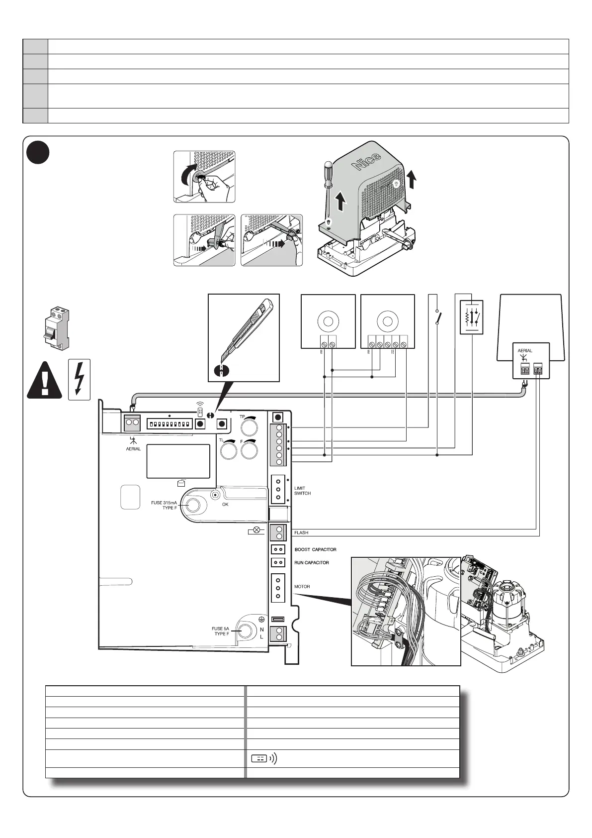
To make the electrical hookup, proceed as described below with reference to g. 7:
01. Unlock the gearmotor
02. Open the cover: remove the two screws and lift the casing
03. Run the power cable through the hole (leave 20/30 cm of free cable) and connect it to its terminal clamp
04. Run the cables of the equipment to be installed or already present through the provided hole (leave 20/30 cm of free cable) and connect
them to their terminal clamps (see g. 7)
05. Perform the desired programming: chapter 7
7
PROGRAM SWITCH
LED RADIO R
RADIO
SbS
IBT4N
FLASH
230 V
2
LED FCA
LED FCC
LED SbS
LED PHOTO
LED STOP
LED:
1
1234
5 678910
5421
NO
NO
NC
8k2
NO
12 13
11
10
9
8
PROGRAM
TLM
TLM
RX
21 543
24V
24V
0V
0V
24V
TX
1 2
1
2
4
3
AERIAL = AERIAL LIMIT SWITCH = LIMIT SWITCH
PROGRAM SWITCH = MICRO SWITCHES FLASH = FLASHER
LED RADIO = RADIO LED BOOST CAPACITOR = BOOST CAPACITOR
LED PHOTO = PHOTOCELL LEDS RUN CAPACITOR = RUN CAPACITOR
LED SbS = STEP-BY-STEP LED MOTOR = MOTOR
LED OK = OK LED FUSE = FUSE
SbS = STEP BY STEP KEY
= RADIO KEY
PROGRAM = PROGRAMMING KEY