EasyManua.ls Logo

Nice TOO3000 - User Manual

Nice TOO3000
16 pages
Print Icon
To Next Page IconTo Next Page
Loading...
Nice
Swing gate opener
TOO3000
TOO3024
TOO4500
TOO4524
TOO3000/V1
TOO4500/V1
EN - User, installation and safety instructions

Other manuals for Nice TOO3000

Question and Answer IconNeed help?

Do you have a question about the Nice TOO3000 and is the answer not in the manual?

Summary

Swing Gate Opener Operation

General Warnings: Safety, Installation, Use

Installation Warnings

Critical safety instructions and precautions to follow before and during the installation process.

Product Description and Intended Use

Installation

Manually Releasing the Gearmotor

Procedure for manually disengaging the gearmotor to allow manual gate operation.

Manually Locking the Gearmotor

Procedure for manually re-engaging the gearmotor for automated operation.

Electrical Connections

Automation Testing

Testing Procedures

Steps to follow for testing the automation system's functionality and safety.

Commissioning

Final steps for enabling system use after successful testing and setup.

Maintenance

Technical Specifications

Overview

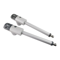
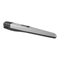
This document describes the Nice TOO series of electromechanical gearmotors for automating swing gates. The manual provides essential information for safety, installation, use, and maintenance of these devices.

Function Description

The Nice TOO series gearmotors are designed to automate swing gates. They are electromechanical devices that operate a worm screw reduction unit to open and close gates. The gearmotors are powered by an external control unit. In the event of a power outage, the gate can be operated manually by disengaging the gearmotor.

The product is available in several versions, catering to different voltage requirements and gate sizes:

  • 24V versions: TOO3024, TOO4524
  • 230V versions: TOO3000, TOO4500
  • 120V versions: TOO3000/V1, TOO4500/V1

For the 24V versions (TOO3024 and TOO4524), it is crucial to note that only the MC424LR01 control unit model can be used.

Important Technical Specifications

The technical specifications vary depending on the model, but general characteristics are provided for an ambient temperature of 20°C (±5°C).

Model-Specific Specifications:

Specification TOO4500 TOO4524 TOO3000 TOO3024 TOO3000/V1 TOO4500/V1
Motor voltage [V] 230 24 230 24 120 120
Frequency [Hz] 50 DC 50 DC 60 60
Max gate length [m] 4.5 4.5 3 3 3 4.5
Max gate weight (kg) 250 250 300 300 300 250
IP protection rating 54 54 54 54 54 54
Operating temperature [C°] -20 to +50 -20 to +50 -20 to +50 -20 to +50 -20 to +50 -20 to +50
Weight of motor [kg] 6 5.5 6 5.5 5.5 6
Speed [m/s] 0.016 0.014 0.016 0.014 0.016 0.016
Travel [mm] 500 500 400 400 400 500
Capacitor [mF] 7 - 7 - 20 20
Nominal current draw [A] 1.1 1.1 1.1 1.1 1.1 1.1
Maximum current draw [A] 1.5 5 1.5 5 1.5 1.5
Nominal power draw [W] 250 30 250 30 250 250
Maximum power draw [W] 340 120 340 120 340 340
Nominal force [N] 300 300 300 300 300 300
Maximum force [N] 2000 1800 2000 1800 2000 2000
Cycles (cycles/hour) 24 continuous 24 continuous 24 24
Control unit A60 MC424L (230V), MC424L/V1 (120V) A60 MC424L (230V), MC424L/V1 (120V) A60/A/V1 A60/A/V1
Dimensions [mm] 800 x 100 x 177 h 800 x 100 x 177 h 700 x 100 x 177 h 700 x 100 x 177 h 700 x 100 x 177 h 800 x 100 x 177 h

Dimensions for Rear Bracket Position: The position of the rear bracket significantly influences the gate's opening movement and the force exerted by the motor. The manual provides a table detailing the "A" and "B" dimensions (likely related to the mounting points) for different opening angles (90° and 110°) across various models. For example:

  • TOO3000 - TOO3024 - TOO3000/V1:
    • 90° opening: A=95, B=270
    • 90° opening: A=195, B=200
    • 110° opening: A=150, B=150
  • TOO4500 - TOO4524 - TOO4524/V1:
    • 90° opening: A=200, B=250
    • 110° opening: A=170, B=170

Usage Features

The gearmotors are designed for ease of use and safety, with provisions for manual operation and integration with various accessories.

Manual Release and Locking: In case of power failure or for maintenance, the gearmotor can be manually released and locked.

  • Releasing: Raise the rubber cap, insert the provided wrench, and rotate it clockwise by 90°. This allows the gate to be moved by hand.
  • Locking: Manually move the gate to the halfway open position, raise the rubber cap, insert the provided wrench, and rotate it counter-clockwise by 90°.

Optional Accessories: The system can be enhanced with various Nice accessories, including:

  • Electromechanical gearmotors (a)
  • Vertical electric lock (b)
  • Photocell pair (c)
  • Mechanical limit switch pair (opening) (d)
  • Photocell pillars (e)
  • Flasher (f)
  • Keyswitch/digital keypad (g)
  • Control unit (h) (A60 for TOO3000-TOO4500, MC424 for TOO3024-TOO4524, A60/V1 for TOO3000/V1-TOO4500/V1)

Specific optional accessories are available for 230V/120V and 24V versions:

  • 230V/120V versions: PLA10, PLA11
  • 24V versions: PLA10, PLA11, PS124

Maintenance Features

Regular maintenance is crucial to ensure the safety, reliability, and operational longevity of the automation system.

Periodic Maintenance (Recommended every 6 months for normal domestic use):

  • Disconnect all power supplies: Always disconnect the electrical power supply, including any backup battery, before performing maintenance.
  • Check for deterioration: Inspect automation system components for erosion or oxidation, especially structural parts. Replace any parts that do not meet the required standards.
  • Tighten fasteners: Ensure all screw fasteners are fully tightened.
  • Check moving parts: Inspect for wear on moving parts and replace any worn components.
  • Reconnect power: After completing checks, reconnect power supplies and perform all tests described in the "Automation Testing" chapter.

User-Performable Maintenance: The only maintenance operation recommended for the user is the removal of leaves or debris that might obstruct the automation's movement. All other maintenance, checks, and repairs should be performed by qualified personnel.

Important Notes:

  • No unauthorized modifications: Users should not modify the system or its programming/adjustment parameters. The installation technician is responsible for the system's integrity.
  • Documentation: All tests, periodic maintenance, and repairs must be documented by the person who performed them, and these documents should be kept by the system owner.
  • Disposal: At the end of the product's lifetime, it must be disposed of by qualified personnel in accordance with local regulations for recycling and scrapping. The product should not be disposed of as domestic waste due to potentially polluting or hazardous substances.

Safety and Installation Warnings

The manual emphasizes several critical safety and installation warnings:

  • Qualified personnel: Installation, electrical connections, testing, commissioning, and maintenance must be performed exclusively by qualified and skilled technicians in compliance with current legislation and standards (e.g., Machinery Directive).
  • Product suitability: Before installation, verify that the product is suitable for automating the specific gate, referring to the "Technical specifications."
  • Commissioning: The product cannot be used before it has been properly commissioned.
  • Disconnection device: A disconnection device with a contact opening distance for complete disconnection (overvoltage category III) must be provided in the power supply grid.
  • Handling: Handle the product with care to avoid damage from crushing, denting, dropping, or contact with liquids/heat/naked flames.
  • Children safety: Children must not play with the appliance or its fixed control devices. Remote controls should be kept away from children.
  • Thermal cut-off: The appliance must not be powered through an external switching device (e.g., timer) or a regularly switched supply to prevent inadvertent resetting of the thermal cut-off.
  • System checks: Periodically check cables, springs, and supports for imbalances, wear, or damage. Do not use the system if repairs or adjustments are needed.
  • Bystander safety: Keep bystanders at a safe distance from the automated mechanism during operation.
  • Pedestrian gate integration: If the gate has a pedestrian gate, the system must include a control device to inhibit motor operation when the pedestrian gate is open.
  • Control device placement: Control devices should be visible but kept away from moving parts, installed at a height of at least 1.5 m, and inaccessible unless a selector is used.
  • Entrapment prevention: Ensure no entrapment occurs between the driven part and surrounding fixed parts during gate movement.
  • Manual release label: Permanently fix the manual release label near its actuating member.
  • Power cable damage: A damaged power cable must be replaced by the manufacturer or a qualified servicing company.

The manual also includes a CE Declaration of Conformity, affirming that the products comply with relevant European Directives (2004/108/EC EMC and 2006/42/EC MD) and harmonized standards (e.g., EN 61000-6-2, EN 61000-6-4, EN 60335-1, EN 60335-2-103, EN 13241-1, EN 12445, EN 12453, EN 12978).

Nice TOO3000 Specifications

General IconGeneral
BrandNice
ModelTOO3000
CategoryGate Opener
LanguageEnglish

Related product manuals