EasyManua.ls Logo

Nice TITAN12 - User Manual

Default Icon
2 pages
Print Icon
To Next Page IconTo Next Page
Loading...
TITAN12L1, 912L (w/1050)
Swing Gate System
QUICK START
INSTALLATION
GUIDE
11
MX4802-01 Rev. C ©2022
GATE
6”
11”
Weld or clamp pivot arm on gate hinge post for Pull-to-Open (left) or Push-to-Open (right).
Attach Actuator
to Pivot Arm
Attach Actuator to
Gate Bracket
WASHERS
FIGURE 1: INSTALLATION OF ACTUATOR TO PIVOT ARM AND GATE BRACKET
GATE
BRACKET
912L ACTUATOR
ENSURE
LEVEL
PIVOT ARM
6”
13”
PIVOT ARM
PIVOT ARM
GATE
GATE
PIVOT ARM: Push-To-Open
PIVOT ARM: Pull-To-Open
ACTUATOR AND CONTROL BOX INSTALLATION:
HINGE
POST
HINGE
POST
HINGE
HINGE
GATE BRACKET CENTERLINE
Pivot Arm
Top of Pivot Arm
TOP VIEW
TOP VIEW
FRONT VIEW
FRONT VIEW
1/2”
1/2”
Pivot
Arm
1B
1A
2
4
PULL-TO-OPEN:
Fully open gate,
then locate bracket
on gate support.
PUSH-TO-OPEN:
Fully close gate, then
locate bracket on
gate support.
Pull-To-Open
Push-To-Open
Push-To-OpenPull-To-Open
Bracket Position
Bracket Position
GATE OPEN
Ensure actuator arm is fully retracted, then position gate
bracket on gate structural support as shown below:
GATE CLOSED
TOP OF
PIVOT ARM
Afx Gate
Bracket to
gate struc-
tural support
by welding
or using
bolt/nut.
5
7 8
9
10
ical release open, manually
push gate to desired close
limit, then push to desired
open limit, and then push
to halfway open position.
Close mechanical release,
but do not lock.
actuator and minimum six feet
away from pivot arm (See FIG-
URE 2).
cable through rubber grom-
mets in bottom of control
box and wire per diagram
at right.
For dual gate, dig trench
across drive and run 2nd
actuator cable through con-
duit.
Open mechanical release on actuator.
2 31
6
3
CAUTION! Do NOT weld while control board is powered!
1/2”x
2-7/8”
PIVOT
BOLT
1/2”x3.5”
BOLT
LOCK NUT
LOCK
NUT
Manually Set Limits:
With actuator mechan-
Mount Control Box
same side as primary
Wire actuator to
control board: Pass
Orange
Orange
White
White
Green
Green
Blue
Blue
Yellow
Yellow
Red
Black
Red Black
NOTE: Dual gate: wire Motor 1 and Motor 2 the same way.
EXTREMELY
IMPORTANT!
Read entire
manual before
attempting the
installation.
This is NOT a
“do-it-yourself”
project. Use a
qualied con-
tractor to install
this system.
Read all safety
information!
Place Battery inside
control box with ter-
minals facing toward the front.
CAUTION! Do not mount the control box where the person using
the push button on box can come in contact with the gate!
5 54 43 3
3
3
2 2
22
1 1
11
Question and Answer IconNeed help?

Do you have a question about the Nice TITAN12 and is the answer not in the manual?

Summary

Actuator and Control Box Installation

Pivot Arm: Pull-To-Open

Weld or clamp pivot arm on gate hinge post for Pull-To-Open.

Pivot Arm: Push-To-Open

Weld or clamp pivot arm on gate hinge post for Push-To-Open.

Attach Actuator to Pivot Arm

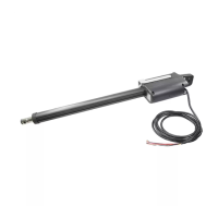
Attach actuator to pivot arm using a 1/2" x 3.5" bolt.

Attach Actuator to Gate Bracket

Attach actuator to gate bracket using a 1/2" x 2-7/8" pivot bolt.

Position Gate Bracket

Ensure actuator arm is fully retracted, then position gate bracket.

Affix Gate Bracket

Affix gate bracket to gate structural support by welding or using bolt/nut.

Mechanical Release

Open mechanical release on actuator.

Manually Set Limits

Manually push gate to desired close and open limits.

Mount Control Box

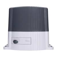
Mount control box on same side as primary actuator, min. six feet away.

Place Battery

Place battery inside control box with terminals facing front.

Wire Actuator

Wire actuator to control board through rubber grommets.

System Configuration and Setup

BlueBUS Photo Eye Locations

Determine BlueBUS photo eye locations and connect to control board.

Attach Warning Signs

Attach warning signs to the gate.

Connect Power

Connect battery, optional power supply, or solar panels to board.

Connect Accessories

Connect audio alarm, safety loops, strobes, and photo eyes.

Program Receiver and Transmitters

Program receiver and transmitters by following specific button press sequences.

Gate Limit Learn Procedure

Test Gate Conditions

Test gate for free travel without binding after removing pivot bolts.

Enter Learn Mode

Enter learn mode by pressing 'ENTER' button.

Adjust Limit Location

Adjust open and close limits by holding OPEN/CLOSE buttons.

Commence Limit Learn

Initiate limit learn sequence by pressing 'OK' in learn mode.

Overview

The Nice TITAN12L1, 912L (w/1050) Swing Gate System is a robust and sophisticated solution designed for automating swing gates. This system is engineered for reliability and ease of use, providing secure and convenient access control for various applications. It is crucial to emphasize that this is not a "do-it-yourself" project and requires installation by a qualified contractor to ensure proper setup and adherence to safety standards. The system's design incorporates features that facilitate both pull-to-open and push-to-open gate configurations, making it versatile for different gate setups.

Function Description:

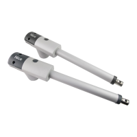
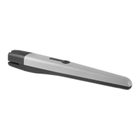
The primary function of the TITAN12L1, 912L system is to automate the opening and closing of swing gates. This is achieved through an actuator mechanism that connects to the gate and a pivot arm, which is securely mounted to the gate hinge post. The system is controlled by a central control board (1050 Control Board) that manages the actuator's movements, interprets commands from various input devices, and ensures safe operation.

The system supports both single and dual gate configurations. For dual gates, two actuators are used, and their movements are synchronized by the control board. The control board is the brain of the system, processing signals from photo eyes, safety loops, transmitters, and other accessories to execute gate operations smoothly and safely.

A key aspect of its functionality is the "Limit Learn Procedure." This process allows the system to accurately learn the gate's full open and close positions, as well as its halfway point. This learning phase is critical for precise gate movement and for setting the operational limits, preventing over-travel and ensuring the gate stops at the desired positions. Once the limits are learned, the system can operate autonomously based on commands.

Safety is paramount in the design. The system integrates with BlueBUS photo eyes, which detect obstructions in the gate's path, preventing collisions and ensuring the safety of people and vehicles. Additional safety devices, such as safety loops, strobes, and audio alarms, can be connected to the control board to enhance the overall safety profile of the gate system. The system also includes a mechanical release mechanism on the actuator, allowing for manual gate operation in case of power failure or maintenance.

The control board also manages power inputs, supporting battery power, an optional power supply, and solar panels, offering flexibility in power sourcing. This ensures continuous operation even during power outages, especially when batteries are connected.

Usage Features:

The TITAN12L1, 912L system offers several user-friendly features that enhance its operational convenience:

  • Versatile Installation: The pivot arm can be installed for both pull-to-open and push-to-open gate configurations. For pull-to-open, the pivot arm is typically mounted 6 inches from the hinge post, extending 13 inches. For push-to-open, it's mounted 6 inches from the hinge post, extending 11 inches. This adaptability makes it suitable for a wide range of gate designs and property layouts.
  • Easy Actuator Attachment: The actuator attaches securely to the pivot arm and the gate bracket using bolts and nuts, ensuring a stable connection for reliable gate movement.
  • Gate Bracket Positioning: The gate bracket's position is crucial for optimal performance. For pull-to-open gates, the bracket is located when the gate is fully open. For push-to-open gates, it's located when the gate is fully closed. This precise positioning ensures the actuator operates within its intended range.
  • Control Box Placement: The control box, which houses the control board and battery, should be mounted on the same side as the primary actuator, at a minimum distance of six feet from the pivot arm. This placement is important for both accessibility and safety, preventing users from coming into contact with the gate while operating the push button on the box.
  • Wiring and Connectivity: The system utilizes a clear wiring scheme for actuators, BlueBUS devices, loop wiring, solar panels, and AC power. Rubber grommets in the control box facilitate cable entry, protecting the wiring. For dual gates, a trench across the drive is recommended for running the second actuator cable through a conduit, ensuring a neat and protected installation.
  • Transmitter Programming: The system supports easy programming of radio receivers and transmitters. Users can program new transmitters by pressing a button on the OXI/A RX unit and then pressing a key on the transmitter, allowing for quick and secure access control setup.
  • Manual Limit Setting: Before the automated limit learn procedure, the gate limits can be manually set. With the actuator's mechanical release open, the gate can be pushed to the desired close and open limits, and then to a halfway open position. This preliminary step helps in fine-tuning the gate's travel range.
  • Learn Mode for Calibration: The "Learn Mode" on the control board allows for automatic calibration of the gate's travel limits. This involves holding down "OPEN" and "CLOSE" buttons to adjust the limit locations, ensuring the gate stops precisely at its open and closed positions. The system then performs a sequence of partial open, slow travel, and full speed movements to finalize the learning process.
  • Safety Device Integration: The control board is designed to integrate various safety devices, including BlueBUS photo eyes, safety loops, strobes, and audio alarms. These devices enhance the safety of the gate system by detecting obstructions and providing warnings.

Maintenance Features:

While the manual primarily focuses on installation, several aspects imply ease of maintenance:

  • Mechanical Release: The actuator includes a mechanical release mechanism. This feature is invaluable for maintenance, allowing the gate to be manually operated for inspection, cleaning, or in case of power failure. It simplifies troubleshooting and ensures the gate remains functional even when automated operation is temporarily unavailable.
  • Accessible Control Board: The control board is housed within a dedicated control box, making it easily accessible for wiring checks, component replacement, or diagnostic procedures. The clear labeling of inputs and outputs on the board (e.g., Motor 1 Inputs, Motor 2 Inputs, Limit LEDs, BlueBUS Connector) aids in quick identification and troubleshooting.
  • Diagnostic LEDs: The control board features various LEDs (e.g., Motor 1 Limit LED, Motor 2 Limit LED, OXI/A RX Green LED) that provide visual feedback on the system's status and operational state. These LEDs are crucial for diagnosing issues, such as whether a limit has been reached or if a transmitter has been successfully programmed.
  • Modular Design: The system appears to have a modular design, with components like the actuator, control board, and various input devices being distinct units. This modularity can simplify maintenance by allowing individual components to be replaced or serviced without affecting the entire system.
  • Battery Backup: The option to connect a battery to the control board ensures that the gate system can continue to operate during power outages. This not only enhances reliability but also reduces the urgency of restoring main power for basic gate functionality, providing a buffer for maintenance scheduling.
  • Clear Wiring Diagrams: The detailed wiring diagrams provided in the manual facilitate accurate installation and make future troubleshooting and maintenance tasks more straightforward. Technicians can easily trace connections and verify proper wiring.
  • Adjustable Force and Speed: The control board allows for adjustments to the gate's force and speed settings. This feature enables fine-tuning of the gate's operation to suit specific environmental conditions or user preferences, potentially extending the lifespan of the mechanical components by preventing undue stress.
  • Regular Inspections: Although not explicitly detailed as a maintenance feature, the emphasis on a qualified contractor for installation suggests that regular professional inspections would be part of the recommended maintenance routine to ensure continued safe and optimal operation of the system. This would include checking mechanical connections, electrical wiring, and the functionality of safety devices.

Nice TITAN12 Specifications

General IconGeneral
ModelTITAN12
CategoryGate Opener
Motor Power Supply24 Vdc
Max Gate Weight1200 kg
Max Gate Length12 m
Protection RatingIP44
Power Supply230V AC
Motor TypeDC Motor

Related product manuals