A (mm) E (mm) E (mm) E (mm)
100 630 595 630 630 630 780 745 780 780 780
110 620 585 620 620 620 770 735 770 770 770
120 610 575 610 610 610 760 725 760 760 760
130 600 565 600 600 600 750 715 750 750 750
140 590 555 590 590 590 740 705 740 740 740
150 580 545 580 580 580 730 695 730 730 730
160 570 535 570 570 570 720 685 720 720 720
170 560 525 560 560 560 710 675 710 710 710
180 550 515 550 550 550 700 665 700 700 700 890
190 540 505 540 540 540 690 655 690 690 690 880
200 530 495 530 530 530 680 645 680 680 680 870
210 520 485 530 530 530 670 635 670 670 670 860
220 660 625 660 660 660 850
230 650 615 650 650 650 840
240 640 605 640 640 640 830
250 630 595 630 630 630 820
260 620 585 620 620 620 810
270 610 575 610 610 610 800
280 600 565 600 600 600 790
2 – English
EN
3.5 - Installation of fixing brackets and gear motor
3.5.1 – Installation of rear fixing bracket
Calculate the position of the rear bracket using graph 2.
This graph serves to establish dimensions A and B and the value of the max-
imum opening angle of the leaf. Important – The values of A and B must
be similar to allow linear movement of the automation.
01. Measure dimension C (fig. 4) on the fixing side;
02. On graph 2, identify dimension C found and trace a horizontal line
that
determines the value of dimension B (*) as shown in the example of fig. 5;
the meeting point with line “r.i.l” (installation line recommended) deter-
mines the value of the angle of maximum opening. From this point, trace a
vertical line
as shown in the example of fig. 5 to determine the value of
dimension A.
If the angle found does not correspond to the requirements, adapt dimen-
sion A and if necessary dimension B, so they are similar.
(*) Do not use values of dimension B below the line “t” (see graph 2).
03. Before being fixed to the wall the bracket must be sealed to the specific fix-
ing plate (fig. 7); if necessary the bracket can be cut adapting values of
dimensions A and B.
Note – The bracket supplied for the Toona series 4-5 gear motor, meas-
ures 150 mm in length; in the event of special applications or in the event
of a gate equipped with external opening (fig. 6) use bracket mod. PLA6
(accessory).
CAUTION! – Before securing the rear bracket, check the fixing zone
of the front bracket is in a solid part of the leaf, as this bracket must
be fixed at a different height of the rear bracket (fig. 8).
04. At this point, fix the bracket using dowels, screws and washers required
(not supplied).
3.5.2 – Installation of front fixing bracket
The front bracket must be fixed to the gate leaf respecting the values of dimen-
sions D and E (Fig. 4).
Note – The bracket supplied for the Toona series 4-5 gear motor must be weld-
ed directly to the gate leaf. If this is not possible, use bracket mod. PLA8
(accessory).
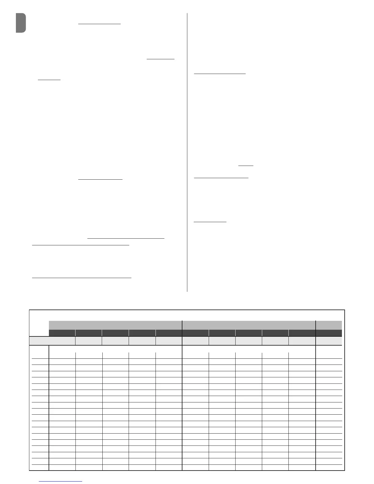
01. Establish the value of dimension E using Table 1;
02. Establish the height in which to position the front bracket, referring to fig. 8;
03. Fix the bracket to the solid part of the gate leaf.
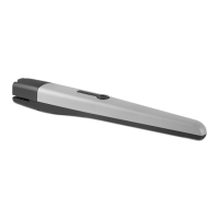
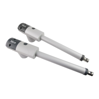
3.5.3 – Installation of the gear motor on the fixing brackets
• Installing the gear motor on the rear bracket:
01. Fix the gear motor to the bracket as shown in fig. 9 using the screw,
washer and nut supplied;
02. Tighten the nut to the end and then loosen by 1/10 of a turn to allow min-
imum clearance between the parts.
• Installing the gear motor
on the front bracket:
01. Fix the gear motor to the bracket as shown in fig. 10 using the screw,
washer and nut supplied;
02. Tighten the screw to the end.
03. Fix the label provided in the package, dealing with the unblocking and
blocking operations of the gear motor, permanently close to the gear motor
3.6 - Setting the mechanical limit switch
The mechanical limit switch allows to set the stop position of the gate leaf, in
this way, it is not necessary to use the stop blocks and the leaf does not hit
against these at the end of the manoeuvre.
• Toona
series 4-5 (24 V)
WARNING – In the event of applications with a gate equipped with open-
ing towards the outside (fig. 6) it is necessary to invert the power supply
wires. Set the limit switch in Opening of the gear motor as follows:
01. Unblock the gear motor as shown in fig. 16;
02. Loosen the mechanical stop screw;
03. Bring the gate leaf manually to the Open position required;
04. Then, bring the mechanical stop to the end of the pin and block the screw
(fig. 11).
05. Bring the leaf manually to the Close position and block the gear motor.
Note – Gear motors mod. TO4006 and mod. TO5016, are provided with a
mechanical limit switch also for the Closing manoeuvre. If in possession of
one of these models, to set the mechanical limit switch repeat the procedure
described above, with a variation at point 03, in this case, bring the gate leaf
manually in the required Closing
position.
• Toona
series 4-5 (230 V)
The Toona series 4-5 gear motors arranged for an alternate current of 230V,
come with mechanical stop with micro switch which, on contact with the pin
interrupts the electrical power supply. WARNING – In the event of applica-
tions with a gate equipped with opening towards the outside (fig. 6) it is
necessary to invert the power supply wires.
• Toona
series 7
Set the limit switch in Opening and Closing of the gear motor;
01. Unblock the gear motor as shown in fig. 16;
02. Move the leaf manually until the mechanical stop screw is visible and
loosen the screw;
03. Bring the gate leaf manually to the Open position required;
04. Then, bring the mechanical stop to the end of the pin and block the screw
(fig. 12);
05. At this point repeat this procedure bringing the leaf manually to the position
of maximum Closure, to set the limit switch in Closure;
06. Finally, block the gear motor.
Toona 4 Toona 5 Toona 7
TO4005 TO4006 TO4015 TO4605 TO4024 TO5015 TO5016 TO5605 TO5024 TO5024I TO7024
D (mm):
730 695 730 730 730 880 845 880 880 880 1070
TABLE 1
 Loading...