EasyManuals Logo

Nice UST1K-2.2kW User Manual

Default Icon
20 pages
To Next Page IconTo Next Page
To Previous Page IconTo Previous Page
Page #6 background imageLoading...
Page #6 background image
6 – English
GB
Connection of direct safety switche
s
T
he safety elements that directly intervene in the control process are
connecte
d
to term
i
na
l
J
10 o
f
term
i
na
l
bl
oc
k
X
2.
Th
e emer
g
ency stop
or safety line attachment, anti-entrapment safety device and safety
d
ev
i
ce
f
or t
h
e w
i
c
k
et
d
oor are
b
etween t
h
em
.
C
onnection of safety switch for wicket door (fi
g
.8
)
Th
e sa
f
ety sw
i
tc
h
i
s to
b
e connecte
d
to term
i
na
l
J
10 term
i
na
l
o
f
te
rmin
a
l
b
l
oc
k X2 in th
e
doo
r
s
with
bu
ilt-in
se
rvi
ce
wi
c
k
e
t
doo
r.
Attention! Remove the
j
um
p
er on J10, if
p
resent
.
C
onnection of the control transmitter for switch with
c
able connected to the ceiling
(
g.8
)
In the UST1K control unit it is
p
ossible to connect a switch with
c
able connected to the ceilin
g
, activated usin
g
traction
(
N
C
c
ontact
)
to terminal J17 of terminal block X4; the function of this
i
n
p
ut corres
p
onds to the
C
L
OS
E-
S
T
O
P-
O
PEN-
S
T
O
P ste
p
b
y
ste
p
c
ontrol
.
B2B1
W
V
J11
J10
Cable slackening /spring
breakage safety or
anti-unwinding safety
switch
U
X2
8
9
Traction
switch
13572468
STOP OPEN Impulse CLOSE
X4
J15 J16 J17 J18
C
onnection of the remote control
(
radio module
)
It is
p
ossible to connect the Nice OXI or OXIFM receiver of the
O
PERA series to the 10 PIN slot
(
J38
)
.
T
o t
hi
s re
g
ar
d
,
i
t
i
s necessar
y
that the side with the programming/
y
LED button faces the internal side of the housin
g.
I
t
i
s necessar
y
to set t
h
e s
p
ec
ifi
c
p
arameters on t
h
e
K
5 mo
d
u
l
e
if
the OXI radio s
y
stem is used
!
F
or more
d
eta
il
s, see t
h
e
i
nstruct
i
ons
f
or us
i
n
g
t
h
e rece
i
ver, manua
l
tr
a
n
s
mitt
e
r
a
n
d
K
5
m
odu
l
e.
O
XI
/
O
XIF
M
/
J
umpers an
d
U
-
b
o
l
ts necessary
f
or contro
l
un
i
t operat
i
on
w
ith com
p
onents not connecte
d
J
umpers:
U
-
b
o
l
ts
:
X
2-
J
1
0
X8
-
Pi
n
5
-
6
X4-
J
1
5
X
9
-Pin 1-
2
X
5-
J
31 8.2
k
Ω
-
Pi
n 1-
2
X6-J33
O
pto-Pin 2-
3
Addi
t
i
ona
l
e
l
ectron
i
c
li
m
i
t sw
i
tx
h
X
7-
J
26,
J
27,
J
2
8
C
onnectin
g
photoelectric barriers
/
pairs of photocells
(
g. 6 a + b
)
I
t is
p
ossible to directl
y
connect a
p
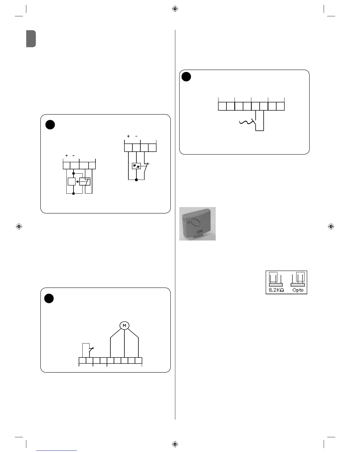
hotoelectric barrier to the UST1K
control unit
(
to terminal block X5
)
to make the passa
g
e safe. If the
i
n
f
rare
d
b
eam o
f
t
h
e p
h
otoe
l
ectr
i
c
b
arr
i
er
i
s
i
nterrupte
d
d
ur
i
n
g
t
h
e
C
L
OS
IN
G
movement of the door
,
it blocks and reverses the direction
t
oward the upper fi nal position.
ATTENTION
:
Th
e sw
i
tc
hi
ng contact an
d
t
h
e pos
i
t
i
ve s
id
e o
f
t
h
e e
l
ectron
i
c
b
arr
i
e
r
system are connected to terminal J30/1 with positive potential in a
one-way photoelectric barrier with only three connection points
.
R
emove t
h
e
j
umper
f
rom term
i
na
l
J
31 o
f
term
i
na
l
bl
oc
k
X
5
if
t
h
e
p
h
otoe
l
ectr
i
c
b
arr
i
er
i
s connecte
d.
7
a
b
21
34
J30
S
Photo
J31
E
S=transmitter
E=receiver
Transmitter and receiver
photoelectric barrier connection
X5
Safety
photoelectric
barrier
¬9'&YROWDJH
power supply
&RQWDFW
RSHQLQJ
21
34
J30
Photo
J31
X5
Reflection photoelectric
barrier connection

Questions and Answers:

Question and Answer IconNeed help?

Do you have a question about the Nice UST1K-2.2kW and is the answer not in the manual?

Nice UST1K-2.2kW Specifications

General IconGeneral
BrandNice
ModelUST1K-2.2kW
CategoryController
LanguageEnglish

Related product manuals