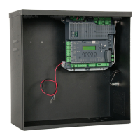
EasyManuals Logo

Nice UST1K-2.2kW User Manual

Default Icon
20 pages
To Next Page IconTo Next Page
To Previous Page IconTo Previous Page
Page #7 background imageLoading...
Page #7 background image
GB
English – 7
Motor cable confi
g
uration
M
ec
h
a
ni
ca
l limit
s
wit
c
h
es
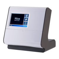
rotoMWire Control station
U1U/11J - 2X
V2V/11J - 2X
W3W/11J - 2X
-Jumper01J - 2X
X7 - J29 Grey
X7 - J34/B Green
X7 - J35/- White
X7 - J34/A Pink
X7 - J29 Yellow
X7 - J35/+ Brown
AMP plug
AMP plug
AMP plug
AMP plug
AMP plug
AMP plug
MECHANICAL LIMIT SWITCH SETTING
Mechanical limit switch setting
A
ttent
i
on
!
Th
e proce
d
ure
f
or sett
i
n
g
t
h
e
li
m
i
t sw
i
tc
h
es
i
s exp
l
a
i
ne
d
on
th
e 5-6 pa
g
es t
h
at
f
o
ll
ow.
T
he sto
p
p
ositions with door in the u
p
/down
p
osition are defi ned
w
i
t
h
sett
i
ng t
h
e
li
m
i
t sw
i
tc
h
es
.
Th
e motor must
b
e e
l
ectr
i
ca
ll
y connecte
d
f
or ma
ki
n
g
t
hi
s sett
i
n
g
.
The limit switch board (
g.11
(
(
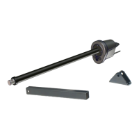
- limit switch board with 8 cams
)
is
a
ccess
ibl
e once t
h
e
li
m
i
t sw
i
tc
h
guar
d
i
s unscrewe
d
.
I
f external control devices are not
y
et connected, it is
p
ossible to
c
ontrol the door with the control unit usin
g
the inte
g
rated OPEN,
C
L
OS
E
a
n
d
S
T
O
P
bu
tt
o
n
s
in
dead
m
a
n m
ode.
I
f the OPEN button is pressed, the door should open; otherwise the
L1 and L2 phases on the control unit must be reversed after havin
g
made sure the volta
g
e has been cut off.
I
f the gearmotor was installed turned 180° (upside-down assembly),
t
he door must also open with the inte
g
rated OPEN button; otherwise
t
he L1 and L2 phases must be reversed in zero volta
g
e conditions
.
I
t
i
s a
l
so necessary to correct t
h
e two emer
g
ency stop
li
m
i
t sw
i
tc
h
es
s
o they trip after the limit switch
.
Determining the lower position of the door
To set the limit switches for the lower position of the door, perform
the following operations ( g. 11):
Move the door to the desired CLOSE position
.
Se
t th
e
co
nt
ac
t
ca
m
3
E
(
white
)
so the limit switch is enabled
.
8
white Additional limit switch 2 CLOSIN
G
7
g
reen Additional limit switch 2 OPENIN
G
6 white Additional limit switch 1 CLOSIN
G
5 green Additional limit switch 1 OPENIN
G
4 red Safet
y
limit switch CLOSIN
G
3 white Limit switch CLOSING
2 red Safety limit switch OPENIN
G
1 green Limit switch OPENIN
G
M
ec
h
an
i
ca
l
li
m
i
t sw
i
tc
h
sett
i
n
g
Small motors - 8 contact cam
s
M
ec
h
an
i
ca
l
li
m
i
t sw
i
tc
h
sett
i
n
g
Lar
g
e motors - 7 contact cam
s
7 white Additional limit switch 2 CLOSING
6 green Additional limit switch 2 OPENIN
G
5 white Additional limit switch 1 CLOSIN
G
4 red Safet
y
limit switch CLOSIN
G
3 white Limit switch CLOSING
2 red Safety limit switch OPENIN
G
1 green Limit switch OPENING
O
ptional
BA
}
OO
11
Mec
h
a
ni
ca
l limit
s
wit
c
h
es
Tighten the fi xing screw
A
.
T
o get accurate a
dj
ustment, use t
h
e
scre
w
B
.
M
ove the door into the desired
O
PENIN
G
p
osition
.
S
et the contact cam
1
E
(g
reen
)
so the limit switch is enabled
.
Tigh
ten t
h
e
x
i
n
g
screw
A
.
T
o
g
et accurate a
dj
ustment, use t
h
e
scre
w
B
.
Th
e sa
f
ety
li
m
i
t sw
i
tc
h
e
s
2 SE
an
d
4 S
E
(red) must be set so they
i
ntervene r
i
g
h
t a
f
ter t
h
e contro
l
li
m
i
t sw
i
tc
h
i
s passe
d.
The safety limit switches 2 S
E
and 4 S
E
(red) are factory-set so
they follow the limit switch at a short distance
.
C
heck the correct position of the fi xing screws after the operation
t
es
t.
Th
e
add
iti
o
n
a
l limit
s
wit
c
h
es
8
P2
a
n
d
7 P2 are closin
g
contacts
w
ith zero potential, and the additional limit switches 6 P
1
and
5
P
1
are switching contacts with zero potential
.
In
au
t
o
m
a
ti
c
m
ode
th
e
limit
s
wit
c
h
6
is used as a
p
reliminar
y
limit
switch. Therefore, it is to be set so that it tri
p
s when the door reaches
a
di
stance o
f
5cm
f
rom t
h
e groun
d.
In
dead
m
a
n m
ode
it is not necessar
y
to set it and it is used as a
c
ontact w
i
t
h
zero potent
i
a
l!
10
Small types Lar
g
e type
s
O
ptional
}
}

Questions and Answers:

Question and Answer IconNeed help?

Do you have a question about the Nice UST1K-2.2kW and is the answer not in the manual?

Nice UST1K-2.2kW Specifications

General IconGeneral
BrandNice
ModelUST1K-2.2kW
CategoryController
LanguageEnglish

Related product manuals