EasyManua.ls Logo

Nice UST1K-2.2kW - User Manual

Default Icon
20 pages
To Next Page IconTo Next Page
Loading...
GB
English – 1
UST1K
Instructions and information for installation and use
T
he entire instruction manual is made up of instructions for using the motor and its control unit.
Automatic industrial door control unit
UST1K-1.1kW
UST1K-2.2kW
UST1K-5.5kW
Ni
c
e
Question and Answer IconNeed help?

Do you have a question about the Nice UST1K-2.2kW and is the answer not in the manual?

Nice UST1K-2.2kW Specifications

General IconGeneral
BrandNice
ModelUST1K-2.2kW
CategoryController
LanguageEnglish

Summary

General Safety Rules

Strict Safety Instructions

Details crucial safety instructions for electrical connections and outdoor cable protection.

Control and Connection Elements

Mechanical Limit Switch Setting

Setting Limit Switch Positions

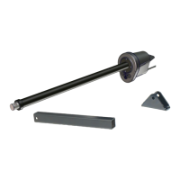
Explains the procedure for setting limit switches to define door stop positions.

Determining Lower Door Position

Step-by-step guide to set the limit switches for the door's lower position.

Single-Phase Motor Wiring

Assembly and Setting Procedures

Setting Final Positions via DIP Switches

General instruction to set DIP switches for final position configuration.

Upper and Lower Final Position Setting

Detailed steps for setting the door's upper and lower limit positions.

Final Positions Adjustment and Checks

Precision Adjustment of Final Positions

Fine-tuning the upper and lower final positions using DIP switches and T2 button.

Electronic Limit Switches and Terminals

Automatic Functions and Display Settings

DIP Switch Functions for Settings

Details how DIP switches control final position setting, precision, and special functions.

UST1 K-1.1 kW Wiring Diagram and Board Layout

UST1 K-2.2 kW;5.5 kW Wiring Diagram and Board Layout

Main Board Component Layout

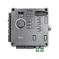
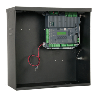
Overview of all terminals and connectors on the UST1K 2.2kW/5.5kW main board.

UST1 K-1.1 kW Electronic Board Details

UST1 K-2.2 kW;5.5 kW Electronic Board Details

Component Identification

Labeled diagram identifying components and connection terminals on the 2.2kW/5.5kW board.

Related product manuals