The provided document is an installation and reference manual for the Apollo 816 LA Linear Actuator, a component of a gate opener system. This manual specifically focuses on the installation of the actuator itself, with control box installation and operation detailed in a separate manual.
Function Description
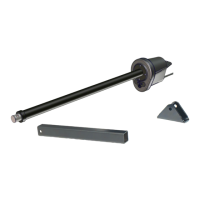
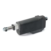
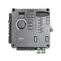
The Apollo 816 LA Linear Actuator is an electromechanical device designed to open and close swing gates. It is a key part of an automated gate system, working in conjunction with a control box (e.g., Apollo 936, 1050, or Mercury 310 controllers) to provide automated gate operation. The actuator is responsible for the physical movement of the gate leaf, extending and retracting to pull or push the gate open or closed. It incorporates internal limit switches that need to be set during installation to define the gate's open and close positions.
Important Technical Specifications
- Drive Type: Electromechanical
- Gate Length Max: 16 ft (5 M) Leaf
- Gate Weight Max: 600 lb (272 Kg)
- Open/Close Time (To 90°): 14 - 16 seconds (Adjustable)
- Temperature Rating: -4° to 122° F (-20° to 50° C)
- Operating Voltage: 12 VDC
- Actuator Dimensions: 42 inches Retracted - 66 inches Extended
- User Controls: Compatible with 936, 1050, or Mercury 310 Controllers
- Listed To UL325: 936, 1050, and Mercury 310 Controllers: Usage Class I, II
Usage Features
The Apollo 816 LA Linear Actuator is designed for both "pull-to-open" and "push-to-open" gate configurations.
Installation Flexibility:
- Pivot Arm Mounting: The pivot arm, which connects the actuator to the gate, can be securely mounted to the hinge post. Welding is the preferred method for mounting the pivot arm, but an optional bolt-on pivot arm (P/N 446) is available if welding is not possible.
- Actuator to Pivot Arm Mounting: The actuator mounts to the pivot arm using a bolt, washer, and lock nut. Proper tightening of the lock nut is crucial to prevent movement or shifting and to minimize "bounce" or "wobble" when the gate stops.
- Gate Bracket to Actuator Arm Affixation: The gate bracket can be affixed to the actuator arm using either a 1/2" x 3" bolt, washer, and lock nut for maximum security, or a quick-release hitch pin with an R-clip for easy manual opening in case of power failure.
- Gate Bracket Positioning: The gate bracket is positioned on the gate's structural supports (not pickets) when the actuator arm is fully retracted. Its exact location may require tack welding or clamping until the gate can be tested. The bracket centerline should be 1/2" above the top of the pivot arm.
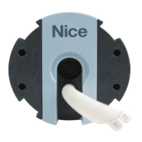
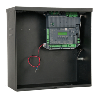
- Cable Routing: Actuator cables are run to the control box through drilled holes (with rubber grommets) in the control box. For dual gate installations, a trench is dug across the driveway to accommodate the longer harness cable from the farthest actuator, with the cable run through appropriate conduit.
Limit Setting:
- The actuator features two internal limit switches, which are adjusted using "Extend Screw" and "Retract Screw" on the rear of the motor. These screws define the gate's fully retracted (closed) and fully extended (open) positions.
- The limit setting procedure involves running the gate to desired positions and adjusting the screws based on whether the gate stops prematurely (with limit LED indication) or moves past the desired position (without limit LED indication).
- Each 360-degree rotation of a limit screw corresponds to approximately 0.2 inches of gate movement.
- For 936 and 1050 controllers, limit LEDs indicate the gate's position (red for close limit, green for open limit on 1050; red for both on 936). For Mercury 310 controllers, both limit LEDs light up when either limit is reached, and the controller chirps twice when LEDs turn on.
Safety Features:
- The manual emphasizes the importance of professional installation by a qualified gate operator company.
- It warns against welding parts to the gate or posts when the control board is powered to avoid irreparable damage.
- It advises disconnecting power at the control panel before making electrical connections.
- Users are cautioned to be aware of all moving parts and avoid pinch points.
- A critical warning states not to extend the 816 extension tube too far to avoid damage, with a maximum tube length of 66 inches (1.65 m).
Maintenance Features
While the manual primarily focuses on installation, it indirectly touches upon maintenance aspects through its warnings and instructions:
- Proper Installation for Reliability: The introduction highlights that "proper selection, system design, installation, and maintenance" contribute to years of reliable operation. This implies that correct installation, as detailed in the manual, is foundational to minimizing future maintenance issues.
- Limit Switch Adjustment: The process of setting and re-setting the open/close limits is a form of calibration that might be required during maintenance or troubleshooting to ensure the gate operates within its intended range.
- Quick Release Hitch Pin: The option to use a quick-release hitch pin for the gate bracket connection facilitates manual operation of the gate in case of power failure or other system malfunctions, which can be a crucial maintenance or emergency feature.
- Warranty Information: The comprehensive warranty section outlines the terms and conditions for repair or replacement, which is relevant for addressing device failures and understanding the scope of manufacturer support. It also mentions that components subject to normal wear (chains, belts, idler wheels, sprockets, fuses) have a shorter warranty period, indicating that these might be expected maintenance items.
- Software Updates: The warranty section notes the responsibility of the Distributor, Dealer/Installer, or End User to ensure the software version in the product is maintained to the latest revision level, suggesting that software updates are part of ongoing system maintenance.