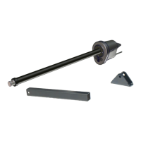
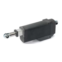
Apollo 816 LA Linear Actuator
Installation Reference Manual
2222
HINTS
• Check limit position is set correctly by using the arrow buttons to jog the gate to mid-position and
then to the limit. For Limit LED behavior, see DETAIL A in Diagram 6-1 and Fig-11B below (and
note).
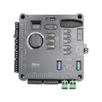
• Mercury 310 controller will chirp twice when Limit LEDs turn ON, and once when Limit LEDs turn o.
11B
816 LIMITS: MERCURY 310
6.2 816 LIMITS: MERCURY 310
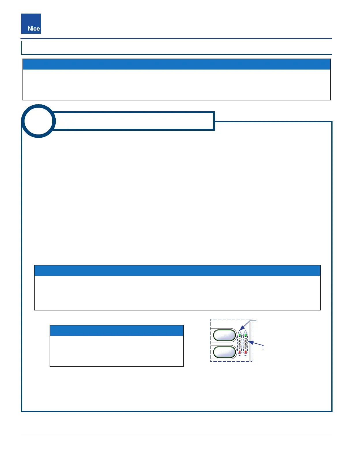
Fig-11B: Mercury 310 Limit LEDs
NOTES
When the actuator reaches either limit during
this procedure, both Limit LEDs (Open and
Close) light up for that actuator (Motor 1 or 2).
IMPORTANT!
These instructions are ONLY for adjusting the location of limit sensors inside the Apollo
816 actuator. After setting these limits, see the “Learn Limits” procedure in the appropriate
controller manual for instructions on how to enable the controller to “learn” these limits.
1. Remove plastic caps from the Extend and Retract limit screws on the Apollo 816 actuator motor (Fig-11).
2. Place Mercury Function Knob to LRN MOTOR 1 or LRN MOTOR 2 (L1 or L2 shows in controller display).
3. Press/hold Left/Right arrow button to run gate to mid-position.
4. Press/hold Left/Right arrow button to run gate to a desired gate limit position.
5. If gate does not stop at desired limit position, adjust per one of the following two scenarios (A or B):
A. If gate moves to preferred gate limit position without stopping (with NO limit LED indication), use
buttons to move gate to preferred limit position, note if actuator arm is extended or retracted, then
adjust limit screw per Scenario A in Diagram 6-1.
B. If gate stops before preferred gate limit position (with limit LED indication), press gate button again to
to move gate to desired limit position, note if actuator arm is extended or retracted, then adjust limit
screw per Scenario B in Diagram 6-1.
6. To set the other limit, run gate to mid position, then to the other limit and repeat from Step 5.
7. After limits are set, replace black plastic caps over 816 actuator Extend and Retract limit screws. If a dual
gate installation, ensure limits are set for each actuator per the above steps.
OPEN
CLOSE
MOTOR 1
Limit LEDs
MOTOR 2
Limit LEDs
www.ApolloGateOpeners.com | (800) 878-7829 | Sales@ApolloGateOpeners.com