English – 25
8
FURTHER DETAILS
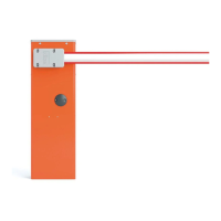
8.1 - Connecting a radio receiver
The control unit has an SM connector for connection of an SMXI, SMXIS, OXI, OXIT or similar radio receiver (not supplied).
Table 6 describes the actions taken by the control unit according to the enabled outputs or commands sent by the radio receiver.
To connect the radio receiver see Fig. 6.
6
Table 6
Output Command description
1 Step-by-step
2 Stop
3 Open
4 Close
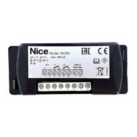
8.2 - Power for external devices
To provide power to the external devices (a radio receiver, or back-lighting for a key switch), you can connect
the device to the product's control unit as shown in the gure below.
15
14
13
12
111098765
24 V (30 Vac max)
0
The power supply voltage is 24V -30% to +50% with a maximum available current of 200 mA.
Red
Light
Green
Light
Operation
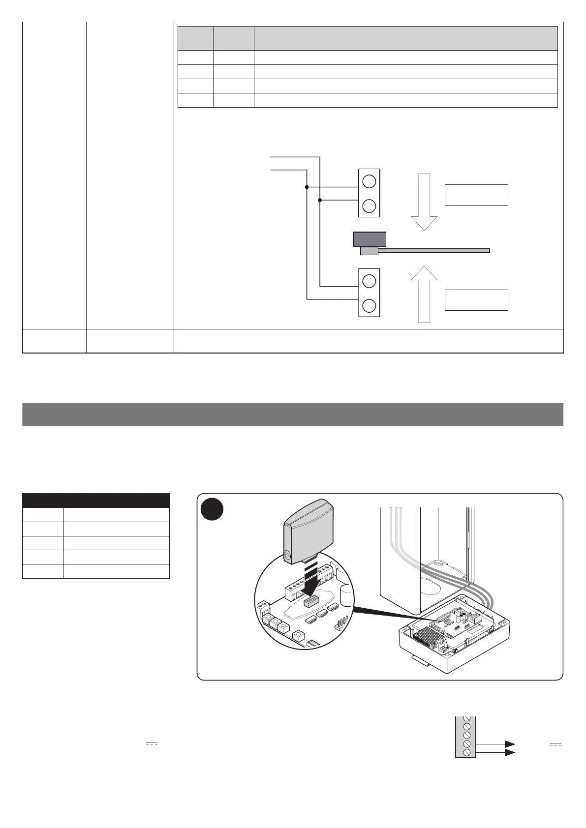
OFF OFF boom closed - no transit in either direction
OFF ON boom open - transit free
ON OFF boom open - transit occupied
ON ON boom closing or transit not controlled
The 'S.C.A.' and 'Courtesy Light' outputs can command small lamps with 24 V DC (total maximum of
10 W per output). If you need to use lamps with higher wattage, you must use relays driven by outputs
on the control unit which in turn control the trafc lights.
S.C.A (9)
S.C.A (9)
R
V
R
ENTRA
WIDE
COMANDO
CON P. P.
ESCE
V
COMANDO
CON P. P. 2
ENTER
EXIT
COMMAND
WITH S.S.2
COMMAND
WITH S.S.
G
G
R
R
OFF S.C.A. and courtesy
light
Trafc light disabled: the S.C.A. and the courtesy light assume factory settings