1
INTRODUCTION
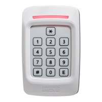
The Presco™ Digital Door Access Decoder utilises the
latest microprocessor technology to operate most electric
door locking devices on the market. The decoder together
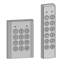
with an encoder (Presco™ keypad (PRE or PSE) or a
Presco™ Interface Module (PIM) with a Clock & Data
(magnetic card format) or Wiegand output reader) offers
access control to restricted areas.
FEATURES
• Split system for maximum security (Encoder & Decoder).
• Door Forced Open detection.
• Door Open Too Long (DOTL) function.
• EGRESS function.
• Automatic door relock function.
• Easy on site programming using Presco™ keypad.
• 400 client programmable users.
• Up to 10 encoders can be connected to one decoder.
• Two Heavy Duty 5 Amp. relay contacts for lock control.
• Can operate Fail Safe or Fail Secure electronic locking
mechanisms.
• Two 1 Amp Normally Open DOTL Alarm relay outputs.
• 10 year non volatile EEPROM memory.
• Operating Temperature Range: 0ºC to 70ºC.
• 36 month (3 year) manufacturer’s warranty.
• Designed and manufactured in Australia.
2
SPECIFICATIONS
Voltage:
Min operating Voltage
1
11 Volts D.C.
14 Volts A.C.
Max operating Voltage
2
30 Volts D.C.
28 Volts A.C.
Current: D.C.
3
40 mA. quiescent.
200 mA. MAX.
A.C.
4
50 mA. quiescent.
240 mA. MAX.
ELC contacts:
(Electric Latch Control)
30 Volt, 5 Amp A.C./D.C. SPST.
Programmable as N.O. or N.C.
DOTL contacts:
(Door Open Too Long)
30 Volt, 1 Amp A.C./D.C. SPST.
Operating Temperature:
0°C to 70°C.
Size: 104mm x 72mm x 27mm.
Weight: 150gms.
1
Operating the unit at a Voltage lower than that specified
may cause intermittent operation possibly resulting in
damage to the unit.
2
Exceeding the maximum specified input voltage may
cause damage to the unit
3
Maximum D.C. current is drawn at 14 Volts input.
4
Maximum A.C. current is drawn at 16 Volts input.
3
TERMINAL DESCRIPTIONS
A general description for each terminal type is given below.
An x has been used in place of a 1 or 2 where a terminal
performs the same function for door 1 and door 2.
GND Negative input (or ground) from the power supply.
AC-DC A.C. 16 - 24 Volt or D.C. 12 - 24 Volt positive input
from the power supply.
DTAx Data line to encoder (white wire on keypads).
LEDx Output to drive a LED to indicate door unlocked.
ELCx (Electric Latch Control) 5 Amp relay output. The
ELC relay is used to control the door
locking/release mechanism. The relay can be
programmed as either Normally Open for fail
secure applications (power applied to open door)
or Normally Closed for fail safe applications
(power applied to lock door).
DOORx This input requires a normally closed switch
connected to ground, typically a reed switch
attached to the door. The DOOR input is used by
the PAC2 to monitor when the door is physically
open (not unlocked). In order to use this input it
must first be enabled (via memory 84, refer to
page 13) and a normally closed (when the door is
closed) door switch (or monitored lock contacts)
must be connected between DOOR and GND.
The DOOR input is used to detect when the door
has been opened for use by the door forced open,
Door Open Too Long and automatic relock
functions.
4
DOTLx (Door Open Too Long) 1 Amp Normally Open
relay output, operates when a DOTL or Door
Forced Open alarm condition occurs.
EGRSx The EGRESS input can take either a normally
open or normally closed switch between EGRESS
and GND. When this input is activated the ELC
relay will come on and remain on for the time that
the EGRESS input is on. Once the EGRESS
input is released the timing set for ELC will begin.
The other selected features of the PAC2 (DOTL,
Door Forced Open & Automatic Relock) will also
become active at this time. Therefore the
EGRESS input can be used to hold the door open
indefinitely with the use of a toggle switch, or with
the use of a momentary type switch it can be used
to release the door for a set time in exactly the
same way that a momentary user code does.
DLOG Data input/output for optional PACDL data logger.