EasyManua.ls Logo

Nidek Medical ME 1200 User Manual

Nidek Medical ME 1200
60 pages
To Next Page IconTo Next Page
Page #1 background imageLoading...
Page #1 background image
This manual is included with the instrument for use by service personnel
during installation.
The contents are not intended for customer use and should only be conducted
by qualified personnel.
INSTALLATION MANUAL
INSTALLATION MANUAL
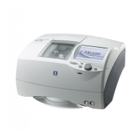
Multifunction edger
Question and Answer IconNeed help?

Do you have a question about the Nidek Medical ME 1200 and is the answer not in the manual?

Nidek Medical ME 1200 Specifications

General IconGeneral
BrandNidek
ModelME 1200
CategoryEdger
BevelingYes
GroovingYes
Safety BevelingYes
MaterialPlastic, Polycarbonate, High-Index
Lens MaterialPlastic, Glass, Polycarbonate
Lens Size Range15-80mm
Power Supply220V, 50/60Hz

Summary

Safety precautions

Installation precautions

1. REQUIREMENTS

1.1 Requirements

Lists necessary tools and materials for installation and adjustment procedures.

2. INSTALLATION PROCEDURE

2.1 Installation Location and Instrument Main Body Movement

Details on choosing a location and safe procedures for moving the instrument.

2.2 Unpacking

2.3 Accessory Check

2.4 Spacer Removal

2.5 Pipe Arrangement

2.5.1 Pump and tank connection diagram

Visual guide for connecting the pump and tank to the main body and water supply.

2.5.2 Pump and tank connection procedure

Step-by-step instructions for connecting the pump and tank components.

2.5.3 Checking the cleaning water and water curtain

Procedure to verify the functionality of water flow for cleaning and curtain.

3. CHECK AND ADJUSTMENT PROCEDURES

3.1 Check and Adjustment Procedure Flowchart

Visual flowchart outlining the sequence of checks and adjustments for the instrument.

3.2 Service mode

3.2.1 Entering service mode

Instructions on how to access the service mode for calibration and adjustments.

3.2.2 Loading the shape for adjustment

3.3 Size Check and Adjustment

3.3.1 Checking the size

Method to measure the outer diameter of a processed lens and verify its size.

3.3.2 Adjusting the size

Procedure to adjust the lens size parameter when it falls outside the specified tolerance.

3.4 Surface Measurement (LMU) Calibration

3.5 Safety Bevel Check and Adjustment

3.5.1 SFB setting

Configuration of safety bevel parameters for different lens types (beveled and flat).

3.6 Drilling Check and Adjustment

3.6.1 Loading the drilling confirmation shape data

Steps to load specific data for verifying drilling accuracy and parameters.

3.6.2 Adjusting the hole diameter

3.6.3 Adjusting the hole depth

3.6.4 Adjusting the hole/slot reference, drill zero point, and drill hole vertical position

3.6.5 Adjusting the front surface offset

3.7 Axis Adjustment

3.7.1 Adjusting the axis shift

Procedure to correct any misalignment in the lens's optical axis.

3.7.2 Safety bevel amount is not consistent

3.8 Polishing Adjustment

3.8.1 Lens edge is left unpolished or burnt

Adjusting polish differential parameters to correct unpolished or burnt lens edges.

3.8.2 One side of beveled edge is left unpolished

3.8.3 Adjusting the polish axis

3.8.4 Adjusting the polish size

3.9 Bevel Position Adjustment

3.10 Groove Position Adjustment

3.11 Groove Depth Adjustment

3.12 Bevel Width and Height Adjustment for Step Beveling (Type PLB-8S only)

3.12.1 Bevel width in step beveling

Procedure to adjust the width of the bevel in step beveling mode.

3.12.2 Bevel height in step beveling

3.13 Clock Check

4. CHECK LIST

4.1 Me 1200 Installation Work Check List

A checklist for verifying proper installation and adjustment of the Me 1200 instrument.

Related product manuals