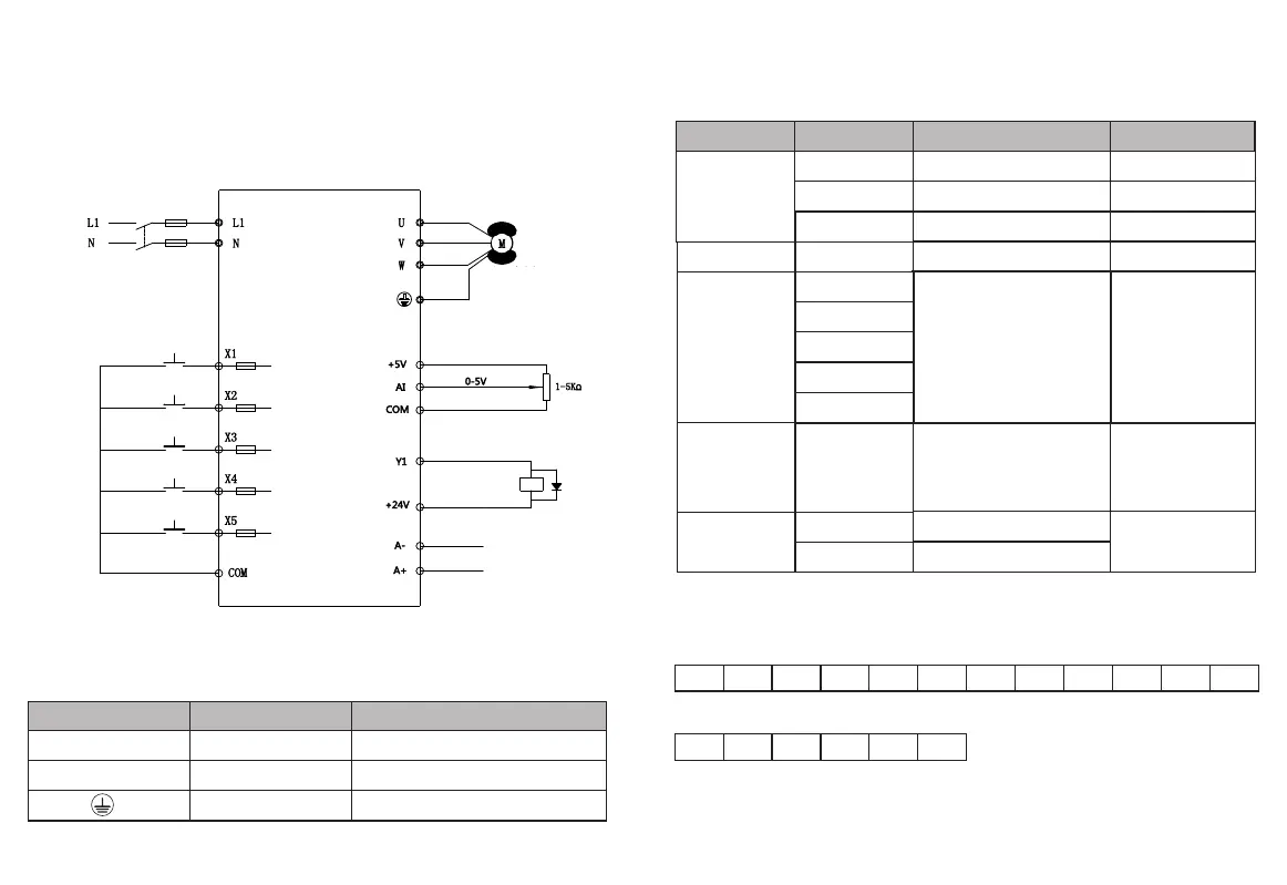
2.1 Con trol Loop Wiring Diagram
2.2 Control Terminals a nd Func ti on Description
Chapter 2 Description of Control Loop
-4--3-
Table2-1 -2 Control Loop Terminal Description
C a t e g o r y
Funct ion Descri ption
Specifications
Terminal Symbol
Power interface
+ 5V Analog Input Terminal Power
Supply
+ 5 V
+ 2 4 V
C O M
+2 4 VDigital signal input terminal
power supply
Analog, Digital, + 5V and + 24V
Ground Reference
Maximum output 100mA
Maximum output 20mA
Analog quantity and digital
quantity share land
A I
AI only receives voltage quantity input
(reference ground: COM)
INPUT, input voltage range:
0 ~ 5V
Analog Input
X 1
Multifunction Input
X 2
X 3
X 4
X 5
Y 1
Multifunctional programmable
open collector output,
programmable The process is
defined as a switching value
output terminal with multiple
functions, Common side: COM
OUTPUT, maximum load
currentNo more than 50mA.
Digital Output
X 1
X (X1, X2, X3, X4, X5) to COM
Active when intermittent shorting
(Common side: COM)
INPUT, 0-10V level signal,
Active low, 5mA.
A +
Rs485 Signal + Terminal
Standard Rs485
communication
interface
Communication
Interface
A -
Rs485 Signal-Terminal
Figure2-1
Table 2-1 Inverter Main Circuit Description
Terminal marking
N a m e D e s c r i p t i o n
L 1、N
Single-phase power
supply input
Single phase2 2 0 VAC power connection point
U、V、W
Frequency converter output Connect three-phase AC motor
Grounding terminal
2.3.1 Screen printing of external control terminals
+5V COM AI A+ A- X1 X2 X3 X4 COM +24V Y1
2.3.2 Screen printing of power board terminals
L1 L2 G U V W
2 . 3 Te r m i n a l S c r e e n P r i n t i n g
Grounding terminal
Multi-function
terminal input
1ph 220v power
supply input 50/60HZ
three phase
asynchronous motor
analog input
Modbus,this
function can not use