Chapter 4 Fu nction Pa ram eter Table
The symbols in the menu are described as follows
Indicates the parameter that can be modified in any state;
Indicates the parameter that cannot be modified in the running state;
Indicates that the parameter is actually detected and cannot be modified;
Indicates that the parameter is "Manufacturer Parameter" and can only be
modified by the manufacturer. Modification is prohibited by the user.
×:
○:
◆:
◇:
Function
Code
N a m e
C o n t e n t
S e t R a n g e
Factor y
Sett ings
Change
F 0 Group-Basic Operating Parameters
F0.00
0: vector control
1: Reserved
2: V/F Control Note:
This parameter cannot be initialized
please modify it manually
Motor control mode
0~2
2
×
F0.01
0: Operation Panel Run Command Channel
1: Terminal Operation Command Channel
2: communication run command channel
Command
Source Selection
0~2 0
○
F0.02
0: given number 1 (preset frequency F0.03,
operation panel key ▲、▼can be modified)
1: The number is given 2 (preset frequency
F0.03, terminal UP/DOWN can be
modified)
2: AI1 analog (0 ~ 20mA/0 ~ 5V)
3: Reservation
: panel potentiometer
5: Reserved
6: Multi-speed
7: Reserved
8: PID
9: given communication
Main Frequency
Source X Selection
0~9 4
○
F0.03
The set value is a given initial value
of the frequency number
Preset frequency
0.00 ~ upper limit
frequency
50.00
○
F0.04
0: In the same direction
1: Opposite direction
0~1
0
Running direction
×
F0.05
The maximum output frequency is
the highest frequency allowed by
the frequency converter and is the
reference for acceleration and
deceleration setting.
MAX{50.00,
F0.06】}
~ 300.00
50
Maximum Frequency
×
F0.06
The operating frequency cannot
exceed this frequency
Lower limit frequency
"F0.07"~
Maximum frequency
"F0.05"
50.00
Upper limi t
freq uency
×
F0.07
The operating frequency cannot be
lower than this frequency
0.00 ~ upper
limit frequency
"F0.06"
0.00
Lower limit
frequency
×
F0.08
For occasions requiring silent
operation, appropriate mention
can be made The high carrier
frequency meets the requirements,
but the carrier frequency is increased
The rate will increase the calorific
value of the frequency converter.
Carrier frequency
2.0~16.0KHz
0.05~4.0KW
6.0KHz
5.5~11.0KW
4.5KHz
15.0~30.0KW
3.0KHz
○
F0.09
The frequency converter accelerates
from zero frequency to the maximum
output frequency Take time
Acceleration time
0.1~6000.0S
0.05~4.0KW
7.5S
5.5~11.0KW
15.0S
15.0~30.0KW
30.0S
○
F0.10
The frequency converter decelerates
from the maximum output frequency
to the zero frequency station Take time
Deceleration time
○
F0.11
0:Operating Frequency
1:Set Frequency
Runtime frequency
instruction
UP/DOWN Benchmar
0~1
0
×
F 1 G r o u p - M o t o r P a r a m e t e r s
F0.09
F0.10
Setting motor parameters
减速时间
○
F1.00
Motor rated power
Rated voltage of motor
Motor rated current
Motor rated frequency
Rated speed of motor
F1.01
F1.02
F1.03
F1.04
0.05~99.99KW
0~999V
0.1~600.00A
0.01Hz~
maximum frequency
0~60000RFM
50.00
×
×
×
×
×
F1.05
Stator resistance of
asynchronous motor
0.001~20.000Ω
×
Setting stator resistance of
asynchronous motor
F1.06
No-load current of
asynchronous motor
0.1 ~ rated current
of motor
×
Setting no-load current of
asynchronous motor
F 2 G roup Auxiliar y Operation Parameters
10.00
F2.00
Inching operation
frequency setting
○
Set inching forward rotation operating
frequency
F2.01
Inching acceleration
time setting
0.1~6000.0S
0.05~4.0KW
7.5S
5.5~11.0KW
15.0S
15.0~30.0KW
30.0S
○
Set inching acceleration time
F2.02
Setting of inching
deceleration time
○
0
F2.03
Shutdown mode
0~1
×
0: Slow down and stop 1: Free shutdown
F2.04
F2.05
F2.06
F2.07
Start frequency of
shutdown DC braking
Stop DC Braking
Waiting Time
Stop DC brake voltage
0.00 ~ upper limit
frequency
0.0~6000.0s
0.0 ~ 50.0% *
motorRated voltage
0.0~100.0s
0.00
0.0
0.0
0.0%
○
○
○
○
-8--7-
Function
Code
N a m e
C o n t e n t
S e t R a n g e
Factor y
Sett ings
Change
Model Setting
Model Setting
Model Setting
Model Setting
Model Setting
Model Setting
Model Setting
Model Setting
Model Setting
Set inching deceleration time
Model Setting
Model Setting
0.00 ~ upper limit
frequency
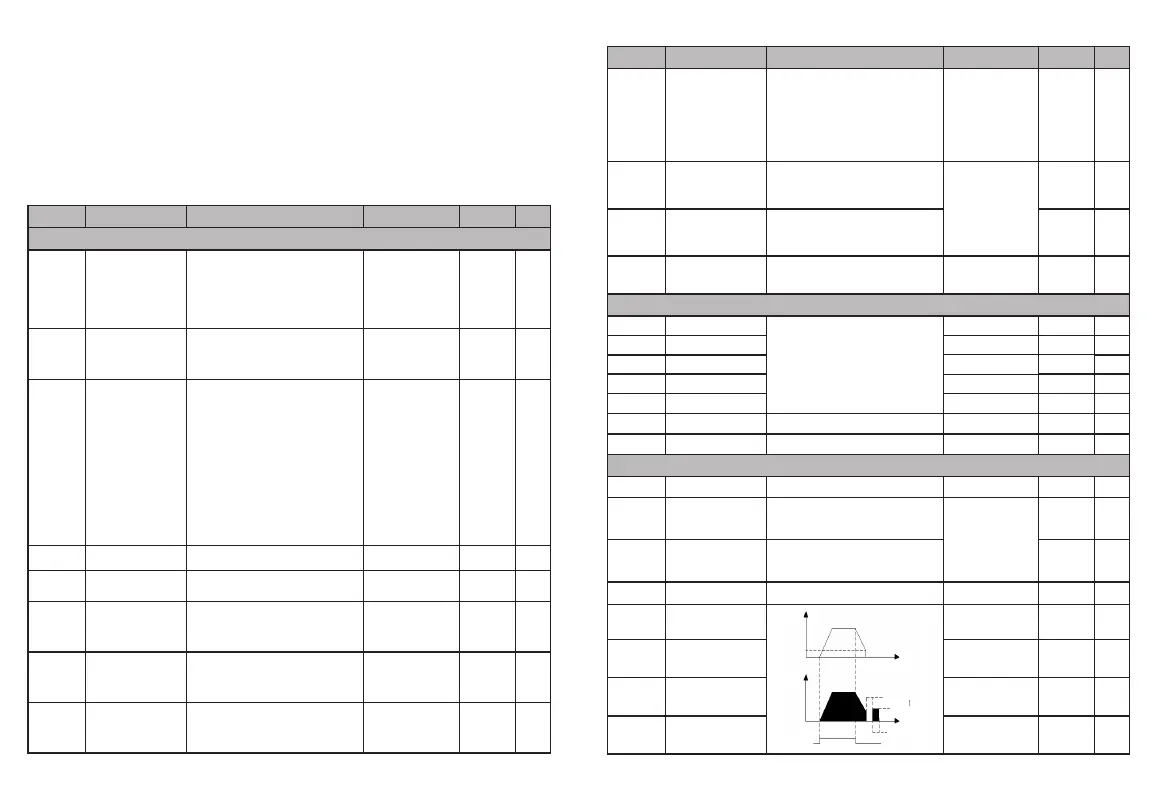
Stop DC braking time
output
frequency
Output current
(effec tive value)
run comma nd
Start Fre quency of stop braking
stop brak ing waiting time
DC Brakin g capacity
stop brak ing time