EasyManua.ls Logo

Nikko Gamma I - Page 10

Default Icon
22 pages
Print Icon
To Next Page IconTo Next Page
To Previous Page IconTo Previous Page
Loading...
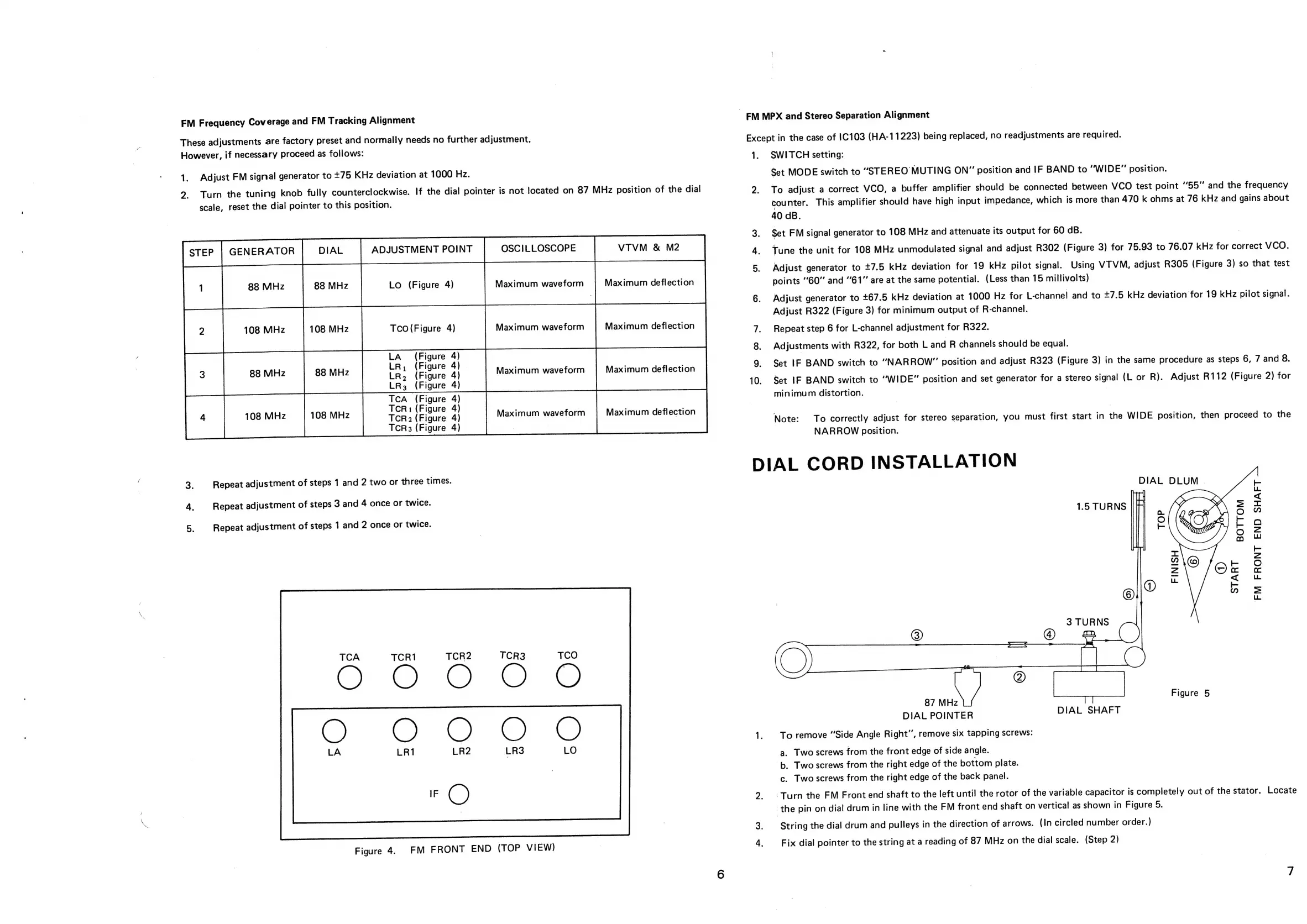
FM
Frequency
Coverage
and
FM
Tracking
Alignment
These
adjustments
are
factory
preset
and
normally
needs
no
further
adjustment.
However,
if
necessary
proceed
as
follows:
1.
Adjust
FM
signal
generator
to
+75
KHz
deviation
at
1000
Hz.
2.
Turn
the
tuning
knob
fully
counterclockwise.
If
the
dial
pointer
is
not
located
on
87
MHz
position
of
the
dial
scale,
reset
the
dial
pointer
to
this
position.
STEP
|
GENERATOR
DIAL
ADJUSTMENT
POINT
OSCILLOSCOPE
i
|
88
MHz
88
MHz
Lo
(Figure
4)
108
MHz
108
MHz
Tco(Figure
4)
LA
cae
7;
LR
igure
3
88
MHz
88
MHz
LR,
(Figuce
4)
LR3
(Figure
4)
TCA
(Figure
108
MHz
108
MHz
VTVM
&
M2
Maximum
deflection
Maximum
waveform
Maximum
waveform
Maximum
deflection
Maximum
waveform
Maximum
deflection
TCR1
(Figure
4)
TCR2
(Figure
4)
TCR3
(Figure
4)
Maximum
waveform
Maximum
deflection
3:
Repeat
adjustment
of
steps
1
and
2
two
or
three
times.
4,
Repeat
adjustment
of
steps
3
and
4
once
or
twice.
5.
Repeat
adjustment
of
steps
1
and
2
once
or
twice.
TCA
TCR1
TCR2
Figure
4.
FM
FRONT
END
(TOP
VIEW)
FM
MPX
and
Stereo
Separation
Alignment
Except
in
the
case
of
1C103
(HA-11223)
being
replaced,
no
readjustments
are
required.
1.
SWITCH
setting:
Set
MODE
switch
to
“STEREO
MUTING
ON”
position
and
IF
BAND
to
“WIDE”
position.
2.
To
adjust
a
correct
VCO,
a
buffer
amplifier
should
be
connected
between
VCO
test
point
“55”
and
the
frequency
counter.
This
amplifier
should
have
high
input
impedance,
which
is
more
than
470
k
ohms
at
76
kHz
and
gains
about
40
cB.
Set
FM
signal
generator
to
108
MHz
and
attenuate
its
output
for
60
dB.
4.
Tune
the
unit
for
108
MHz
unmodulated
signal
and
adjust
R302
(Figure
3)
for
75.93
to
76.07
kHz
for
correct
VCO.
5.
Adjust
generator
to
+7.5
kHz
deviation
for
19
kHz
pilot
signal.
Using
VTVM,
adjust
R305
(Figure
3)
so
that
test
points
“60”
and
61”
are
at
the
same
potential.
(Less
than
15
millivolts)
6.
Adjust
generator
to
+67.5
kHz
deviation
at
1000
Hz
for
L-channel
and
to
+7.5
kHz
deviation
for
19
kHz
pilot
signal.
Adjust
R322
(Figure
3)
for
minimum
output
of
R-channel.
7.
Repeat
step
6
for
L-channel
adjustment
for
R322.
Adjustments
with
R322,
for
both
L
and
R
channels
should
be
equal.
Set
IF
BAND
switch
to
“NARROW”
position
and
adjust
R323
(Figure
3)
in
the
same
procedure
as
steps
6,
7
and
8.
10.
Set
IF
BAND
switch
to
“WIDE”
position
and
set
generator
for
a
stereo
signal
(L
or
R).
Adjust
R112
(Figure
2)
for
minimum
distortion.
Note:
To
correctly
adjust
for
stereo
separation,
you
must
first
start
in
the
WIDE
position,
then
proceed
to
the
NARROW
position.
DIAL
CORD
INSTALLATION
DIAL
DLUM
ha
LL.
:
<
1.5
TURNS
x
Q
za
LL
jj
Zz
©
oO
LL
©
=
3
TURNS
\
®
_@
@e
)
land
oot
Oe
87
MHz
alee
DIAL
POINTER
DIAL
SHAFT
1.
To
remove
“Side
Angle
Right’,
remove
six
tapping
screws:
a.
Two
screws
from
the
front
edge
of
side
angle.
-b.
Two
screws
from
the
right
edge
of
the
bottom
plate.
c.
Two
screws
from
the
right
edge
of
the
back
panel.
9.
+
Turn
the
FM
Front
end
shaft
to
the
left
until
the
rotor
of
the
variable
capacitor
is
completely
out
of
the
stator.
Locate
the
pin
on
dial
drum
in
line
with
the
FM
front
end
shaft
on
vertical
as
shown
in
Figure
5.
3.
String
the
dial
drum
and
pulleys
in
the
direction
of
arrows.
(In
circled
number
order.)
Fix
dial
pointer
to
the
string
at
a
reading
of
87
MHz
on
the
dial
scale.
(Step
2)