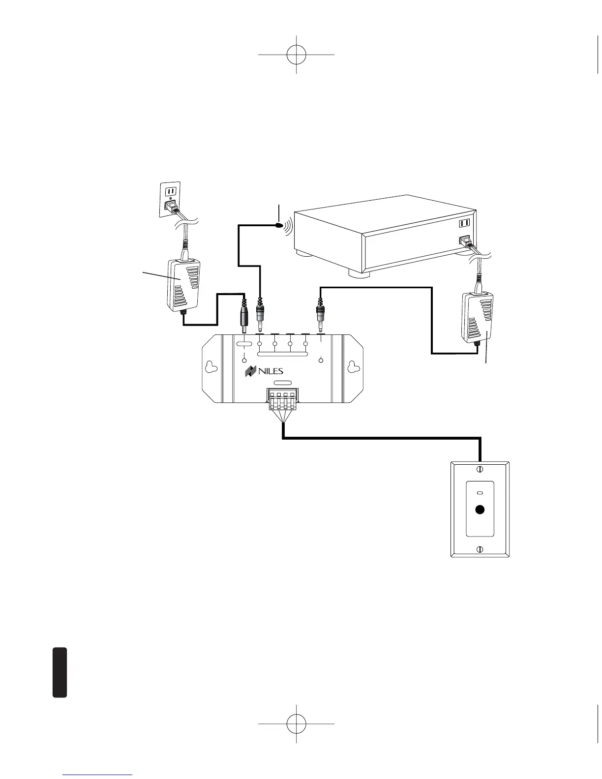
Niles IR
Flasher
MSU140
WS100 IR Sensor
Power, IR data, status signal and ground
via category 5 wire
Stereo Receiver
12V DC power supply
(supplied with the
MSU140 Main
System Unit) plugged
into an unswitched
AC outlet powers
the system
3-30V AC/ DC power supply
(Not Supplied) plugged
into the switched outlet
Niles Stock # FG01035
Figure 1
Connecting the WS100 to a Niles MSU140
Main System Unit broadcasting a status
feedback signal.
In a typical system, the MSU140 provides
for the connection for one remote room
sensor (or keypad) and will control multiple
audio/video components via its flasher
connections.