Sensor/Keypad Cable
The MSU140 connects to IR sensors and the Intellipad with
category 5 cable, with a maximum cable run of 500'.
Flasher Cable
Niles infrared flashers come supplied with a 10 foot 2-con-
ductor 22 gauge cable. Should you need to extend it, use a
16 gauge 2-conductor cable (“zip-cord”). Shielding is not
necessary for a flasher. Flasher wires can be extended up to
200 feet.
8
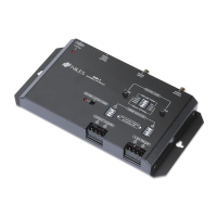
I
NFRARED
M
AIN
S
YSTEM
U
NIT
TOOLS
REQUIRED
• 1/8" Standard
Slotted
Screwdriver
• Wire Stripper
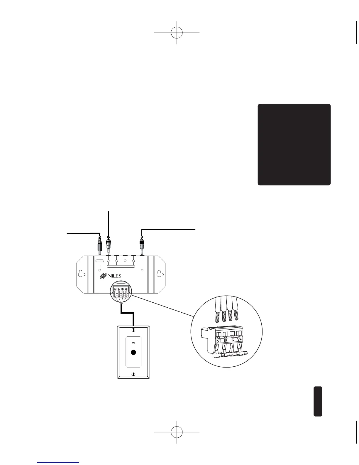
WS100 Sensor
To unswitched
AC Outlet
Figure 6:
MSU140
Installation
MSU140 Sensor
Connection
MSU140
To Niles
IR Flasher
To 3-30V AC/ DC power supply
plugged into a switched
AC outlet.Typically found
on back of a receiver.