Installation
If you are installing the VCS-2D into an existing wall, take
time to consider any possible obstructions which may be
hidden inside the wall, such as wood and metal studs; elec-
trical, telephone or other types of wiring; plumbing; con-
duit; old wall safes; etc.
1. Install the electrical box or p-ring in the usual manner.
2. Run all the necessary wiring to the VCS-2D. Label the
wires for future reference.
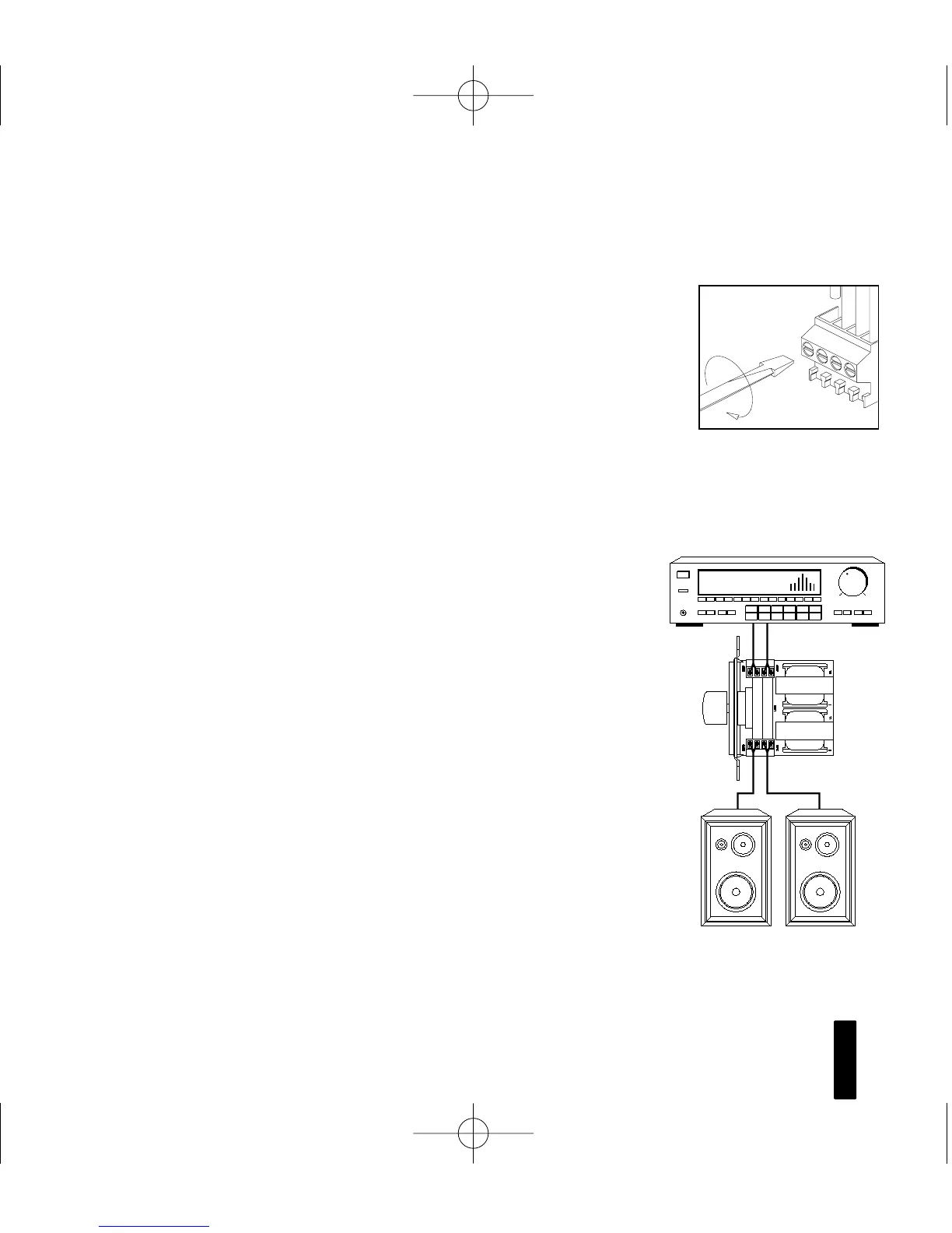
3. Make the connections to the VCS-2D. Locate the con-
nectors for the VCS-2D (remove them if they are plugged
in). Next, strip
1/4” of insulation from the end of each wire.
Tightly twist the end of each wire until there are no frayed
ends. Insert each wire into the appropriate hole on the
removable connector blocks; secure the wiring to the con-
nectors by tightening the small connector screws. Be cer-
tain that proper phasing is observed—connect the positive
terminals on the VCS-2D to the positive terminals on the
amplifier and speakers; the negative terminals on the VCS-
2D to the negative terminals on the amplifier and speakers.
See (Figures 3 and 4).
4. Plug the connectors into the VCS-2D as shown in(Figure 5)
on next page.
The inputs of the VCS-2D are the connector pins
labeled “AMPLIFIER”. The outputs are the connector
pins labeled “SPEAKERS”. Be sure not to reverse these
connections or the VCS-2D will not function properly.
8
PP
RR EE MM II UU MM
SS
TT EE RR EE OO
VV
OO LL UU MM EE
CC
OO NN TT RR OO LL
Figure 3
Wiring the Connectors
VCS-2D
To
Amplifier (Input)
To
Speakers (Output)
Speakers
Receiver
Figure 4
Wiring Diagram
DS00101C/VCS-2D 2/5/99 1:32 PM Page 6