INSTALLATION
1. Locate the connector plugs (and
remove them if they are
plugged in). See Figure 6.
2. Strip 1/4" of insulation from the
end of each wire. Tightly twist
the end of each wire until no
frayed ends remain.
3. Use a small flathead screwdriv-
er or your thumbnail to raise
the locking tabs, exposing the
holes on the removable con-
nector plug.
4. Insert each wire into the appro-
priate hole on the removable
connector plug, and snap the
locking tab down.
NOTE: Maintain proper phasing. Connect the positive termi-
nals on the volume control to the positive terminals on the
amplifier and speakers, and connect the negative terminals on
the volume control to the negative terminals on the amplifier
and speakers. See Figure 3. To help you avoid improper phas-
ing, the connector plug is keyed. Insert the smooth side of the
connector plug into the smooth side of the socket. Don’t force
the scalloped side of the connector plug into the smooth side
of the socket. See Figure 6.
5. Set the Impedance Magnification Switch (See Figure 7) as
determined by the IM charts (Figures 4 and 5).
6. Plug the connectors into the volume control as shown in
Figure 6. The inputs of the IM volume control are the con-
nector pins labeled AMPLIFIER. The outputs are the connec-
tor pins labeled SPEAKERS.
NOTE: If you reverse these connections, the volume control
won’t function properly.
7. Secure the volume control to the junction box. Insert the
1-1/4" device screws into the oblong screw holes on the top
and bottom of the volume control. The oblong shape of the
screw holes helps you place the volume control in a vertical
position. Align the screws with the threaded holes
in the junction box. Tighten the screws using a Phillips
screwdriver. DO NOT OVERTIGHTEN. If necessary, loosen
these screws several turns so the volume control fits flush
with the faceplate.
8. Use the shorter plate screws to fasten the Decora faceplate
to the volume control.
10. Align all the screws in the same direction for a clean,
finished look.
DECORA
®
FACEPLATES
The VCS 100 is designed to use standard and Decora-style face-
plate mounting hardware. You can combine multiple Decora-
style modules (if all are low-voltage controls) within one Decora
faceplate (up to six-gang) with color-matched plate screws.
Decora plates and screws are available from your Niles dealer.
CHANGING THE COLOR OF THE KNOB AND THE
DECORA INSERT
The Decora-style insert and knob on the VCS 100 is removable,
allowing fast and easy color changes as needed. Inserts and
knobs are available in a variety of colors. To change the color of
your unit:
1. Obtain the appropriate knob and Decora-style insert in the
desired color from your Niles dealer.
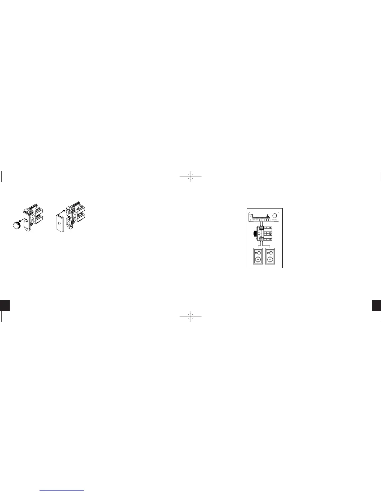
2. Pull the knob off the shaft. See Figure 1.
3. Next, locate the two plastic mounting tabs at the top rear of
the Decora-style insert. Using two fingers, simultaneously
press both tabs down (towards the center of the insert) and
forward (away from you) until the insert pops free from its
mounting slots.
4. Locate the new Decora-style insert. Hold the volume control
facing you. Insert the two bottom tabs into the bottom slots first,
then the two tabs on the top (see Figure 2). Press carefully on
the front of the insert to snap it into place.
5. Locate the new knob. Align its flat side to the flat side of the
shaft, and push the knob onto the shaft. Holding the unit as
shown in Figure 1, check the alignment of the knob by turning
it through all positions.
PREPARING FOR INSTALLATION
Before you install the VCS 100 into an existing wall, consider
the possibility of hidden obstructions inside the wall, such as
wood and metal studs; electrical, telephone, or other wiring;
plumbing; conduit; and old wall safes.
1. Install the junction box in the usual manner.
2. Run all necessary wiring to the volume control. Label the
wires for future reference.
H IGH-PO WER S TEREO V OLUME C ONTROLS
65
H IGH-PO WER S TEREO V OLUME C ONTROLS
Figure 1 Figure 2
VCS100
From Amplifier
(Input)
To Speakers
(Output)
Speakers
Receiver
Figure 3
Wiring Diagram
DS00310BCN/VCS100-VCS100R 11/12/03 10:36 AM Page 7
 Loading...