4
NILFISK LABEL
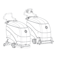
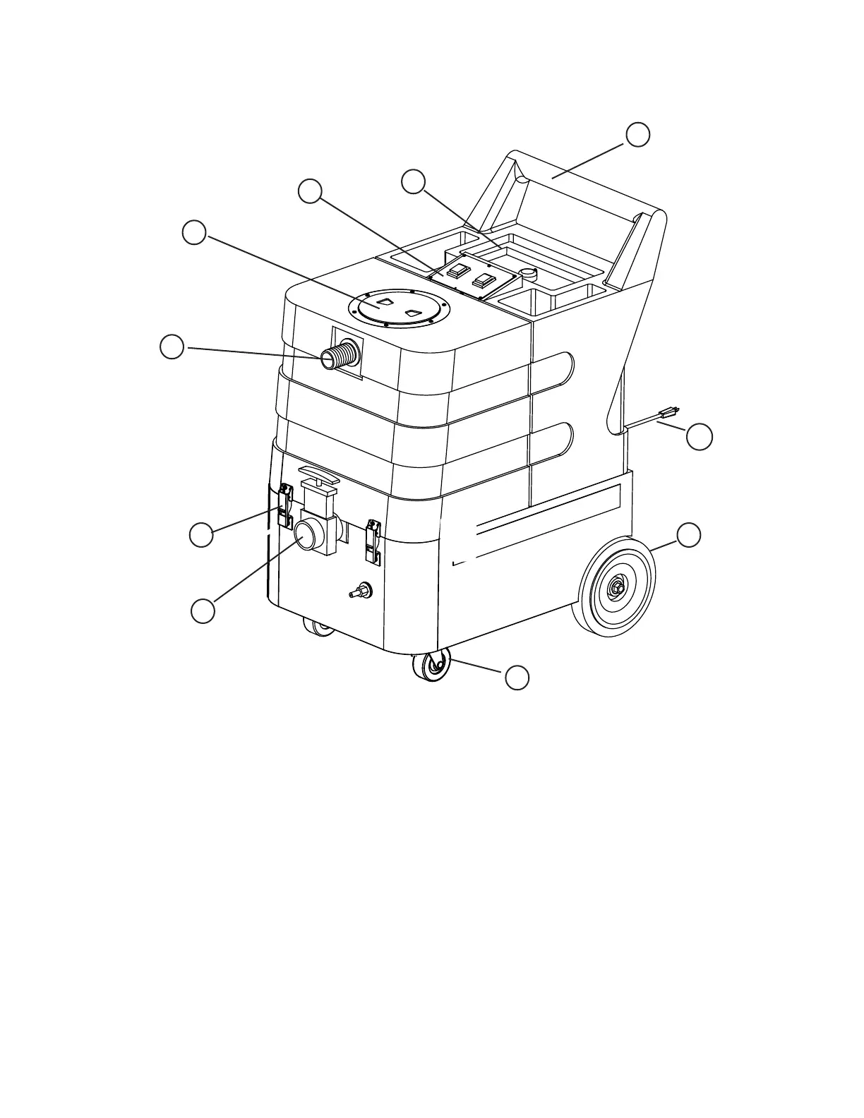
MACHINE DESCRIPTIONS
Operator Handle (1) - Operator holds this to move the machine from one location to another.
Solution Tank Lid (2) - Fill the solution tank here with warm water and chemicals.
Switch Plate (3) - This is where the switches are located that operate the pump, vacuum, and heater.
Recovery Tank Lid (4) - The recovery tank can be cleaned out by running clean water into this opening
with the Drain Gate (7) open. The vacuum float Shut-OFF can also be accessed through this opening for
maintenance.
Vacuum Inlet (5) - This is where the vacuum hose attaches to the machine.
Latch (6) - Open the latches to access the base compartment, which contains the motors and heater.
Drain Gate (7) - Open this gate to drain the recovered solution out of the machine. Be sure to keep this
gate clean.
Castor (8) - The castors swivel for easy maneuvering in tight spots.
Wheel (9) - Large, non-marking wheels for ease of transport.
Power Cord(10) - Two, 7.6 meter cords. Do not use if either cord is damaged.
BECOME FAMILAR WITH YOUR NEW EXTRACTOR
1
2
3
4
5
6
7
10
9
8
 Loading...