This document is a repair manual for Nilfisk P 150.1-10 B and P 160.1-15 B X-Tra high-pressure washers. It provides comprehensive information on safety, technical data, construction, service/repair procedures, operation, and wiring diagrams.
Function Description
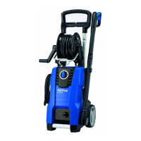
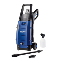
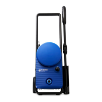
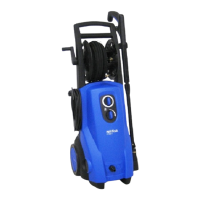
The Nilfisk P 150.1-10 B and P 160.1-15 B X-Tra are high-pressure washers designed for cleaning tasks. They operate by generating a high-pressure water jet, which is effective for removing dirt and grime from various surfaces. The machines incorporate a motor-pump unit that pressurizes water, which is then delivered through a high-pressure hose and nozzle. The operation involves a start-stop system that manages pressure build-up and release, ensuring efficient and safe use.
Important Technical Specifications
The manual provides detailed technical specifications for both models:
Product Segment: Consumer
P 150.1:
- Specification (bar): 140
- Voltage (V): 230
- Frequency (Hz): 50
- Power consumption (A): 12.6
- Power absorbed (KW): 2.9
- Numbers of revolutions (rpm./min.): 2800
- Water volume, HP (l/min.): 6
- Pump pressure (bar): 100
- Nozzle pressure (bar): 94
- Opening pressure (bar): 140
- Retaining time (min.): 5
- Oil contents (ml): 100
- Oil type: Bartran HV68
- Max water inlet temperature (°C): 40
- Max water inlet pressure (bar): 10
- High pressure hose length (m): 6m Textile
- Suction height (m): 1m wet
- Electric cable (m): 5m
- Insulation class: F
- Tightness: IPX5
P 160.1:
- Specification (bar): 150
- Voltage (V): 230
- Frequency (Hz): 50
- Power consumption (A): 13
- Power absorbed (KW): 3.3
- Numbers of revolutions (rpm./min.): 2800
- Water volume, HP (l/min.): 6.9
- Pump pressure (bar): 112
- Nozzle pressure (bar): 106
- Opening pressure (bar): 140
- Retaining time (min.): 5
- Oil contents (ml): 100
- Oil type: Bartran HV68
- Max water inlet temperature (°C): 60
- Max water inlet pressure (bar): 10
- High pressure hose length (m): 8 or 9m textile
- Suction height (m): 1m wet
- Electric cable (m): 5m
- Insulation class: F
- Tightness: IPX5
Usage Features
The manual outlines several operational aspects, including the "Easy Start Guide" and the "Start Stop System Guide," which detail how the machine manages pressure and flow under different conditions:
- Machine Stopped and Outlet Hose Emptied: In this state, the non-return valve is closed, the easy start ball valve is pressed against its upper seat, and the s/s spring presses the s/s piston. The activation arm is in the front position, the micro switch is "on," and the motor runs, but there is no water flow from the nozzle.
- Starting Up (Soft Start): When connecting the machine, the non-return valve remains closed due to insufficient pressure. The easy start ball valve moves slightly from its upper seat. The s/s spring presses the s/s piston, and the activation arm is in the front position, keeping the micro switch "on" and the motor running. Water flows from the inlet to the pump and then through the ball valve back to the water inlet.
- Building-up of Pressure in Hose: During pressure build-up, the non-return valve opens slightly due to high pump pressure. The easy start ball valve moves to the lower seat as the easy start spring is compressed further. The s/s spring continues to press the s/s piston, and the activation arm remains in the front position, keeping the micro switch "on" and the motor running. Water flows from the inlet to the pump, then through the ball valve (decreasing during the process) to the water inlet, and from the pump through the non-return valve to the high-pressure hose.
- Operation (Full Working Pressure): The non-return valve is fully open, and the easy start ball valve is pressed against the lower seat by pump pressure. The s/s spring is slightly pressed, but the activation arm remains in the front position, the micro switch is "on," and the motor runs. The handle is activated, and water flows from the nozzle. Water flows from the inlet to the pump and then through the non-return valve to the high-pressure hose.
- Handle Release: When the handle is released, the non-return valve closes due to pressure in the hose system. The s/s spring is pressed to its maximum position, causing the activation arm to move back and press the micro switch to the "off" position, stopping the motor. Pressure in the pump drops due to a leak in the easy start valve, and the easy start spring presses the ball valve up against the upper seat, closing the cylinder head to the inlet pressure. No water flows from the nozzle.
- Start Stop System Guide: This section illustrates the pressure states at different points (pump, inlet, outlet) during various operational phases: no pressure in the system (3 BAR everywhere), start-up pressure build-up (5 BAR pump, 3 BAR inlet, 5 BAR outlet), pressure build-up to opening pressure (145 BAR pump, 3 BAR inlet, 145 BAR outlet, microswitch activated), motor stop/standby pressure (40 BAR pump, 3 BAR inlet, 40 BAR outlet), pressure in pump during standby (3 BAR pump, 3 BAR inlet, 40 BAR outlet, easy start valve changes position), and gun activated/machine run (3 BAR pump, 3 BAR inlet, 3 BAR outlet when gun activated; 135 BAR pump, 3 BAR inlet, 112 BAR outlet when machine runs).
Maintenance Features
The manual provides detailed instructions for service and repair, emphasizing safety precautions.
Safety Precautions:
- High-pressure jets are dangerous; never direct them at people, pets, live electrical equipment, or the machine itself.
- Operators and bystanders must wear goggles to protect against debris.
- Never clean clothes or footwear while wearing them.
- Children or individuals who haven't read the manual should not operate the machine.
- Do not use the machine in explosive environments.
- Do not clean asbestos-containing surfaces with high pressure.
Dismounting/Mounting Procedures:
- Front Cabinet: Remove 4 Torx screws (TX 20) and 2 screws at the bottom.
- Front Chassis and Motor Cover: Remove 5 Torx screws in the chassis and 8 screws at the bottom.
- S/S Valve: Carefully remove the micro switch box with 2 screws, then remove the S/S valve. When mounting, ensure the micro switch is properly positioned and press down the micro switch arm with a screwdriver.
- Oil Seal: Tip up the oil seal with a screwdriver and discard. Clean and lubricate before mounting. The oil level should be 100 ml.
- Suction and Pressure Valves: Remove valve seats with a tool and discard. Mount new valves with slight finger pressure and a special tool (no. 1220103). Clean and lubricate before mounting. When mounting the cylinder head, tighten bolts in a specific order: Torque 16 Nm for some bolts, and Torque 10 Nm for others, using Loctite 271.
- Wobble Disc: Bearing tracks vary between models (P 150.1 and P 160.1 have different inner diameters). Ensure the correct wobble disc fits. Wobble discs are marked for specific pressures: 150 bar ("1-1" or "1-2") and 160 bar ("2-1" or "2-2").
- Easy Start Valve: Remove the easy seat with a small hook, then remove the O-ring underneath the seat with a small screwdriver. When mounting, place the ball on the end of the spring, ensuring it is in the correct position before mounting the plug. The manual also references an "Operation guide" section 2.5 "Handle release" for further details on the seat mark.
Torque Specifications:
- Specific components require precise torque settings during assembly: 20 Nm with Loctite 271 for some parts, 16 Nm for others, and 10 Nm for certain bolts.
The manual also includes detailed exploded views of the cabinet parts and the motor pump unit, along with wiring diagrams (Circuit Diagram and Wiring Diagram) to aid in assembly, troubleshooting, and repair. The wiring diagrams use standard electrical symbols and color codes (e.g., brown, blue, black, yellow, green, white) with translations in Danish, English, German, and French.