Do you have a question about the Nilfisk-Advance E130.3 and is the answer not in the manual?
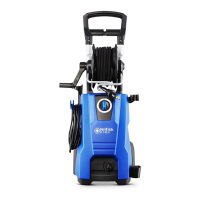
Overview of cabinet components with torque specification for plastic screws.
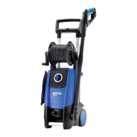
Exploded view and parts list for the hose reel assembly.
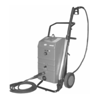
Detailed view of the motor and pump unit with assembly torque and glue specifications.
Instructions for removing and reattaching the front cabinet, including screw details.
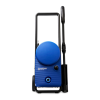
Procedure for removing and installing the pump cover, noting foam and air barrier placement.
Steps for removing and installing the start/stop valve, including tool and torque information.
Instructions for removing and remounting the switchbox cover, emphasizing wire placement and foam.
Steps for removing the motor/pump unit, including wire disconnection and screw removal.
Procedure for removing and reinstalling the main power switch, noting wire and position details.
Procedure for accessing the motor/pump unit and removing the internal hose using a U-pin for X-TRA models.
Steps to remove the MPU back cover and access the internal hose for X-TRA models.
Instructions for removing the telescopic handle and loosening the hose reel from the cabinet.
Procedure for removing the TORX screw and U-pin to access the hose router.
Steps for removing the hose from the internal hose and dismounting screws from the aluminium hose guide.
Instructions for greasing the nipple, connecting the hose, and mounting the hose reel holder.
Procedure for disassembling and reassembling the easy start valve, listing parts order and torque.
Steps for mounting the NRV and spring behind the water outlet, ensuring correct spring placement.
Instructions for mounting the bearing system and the ball ring, noting oil level and open pump view.
Guidance on placing suction valves correctly with respect to guidance and verifying valve levels and O-ring.
Procedure and values for measuring the resistance of the electrical motor, identifying connection plugs.
List of recommended and alternative oil types for the pump, including initial fill quantity.
Types of grease recommended for o-rings and moving parts, and stationary o-rings.
Specification of recommended adhesives for locking aluminum plugs in the pump.
List of required tools for maintenance and repair, including screwdrivers, spanners, and hex wrenches.
Diagram and explanation of the motor pump system when the machine is stopped and the hose is empty.
Diagram and explanation of the motor pump system during normal machine operation.
Diagram and explanation of the motor pump system when the machine is in standby mode.
Schematic showing the electrical connections and components of the motor and switches.
Detailed circuit schematic illustrating the flow of power through switches, motor, and thermal protection.
| Pump Pressure | 130 bar |
|---|---|
| Motor Power | 1800 W |
| Voltage | 230 V |
| Frequency | 50 Hz |
| Max. Inlet Temperature | 40°C |
| Metal Pump | Yes |