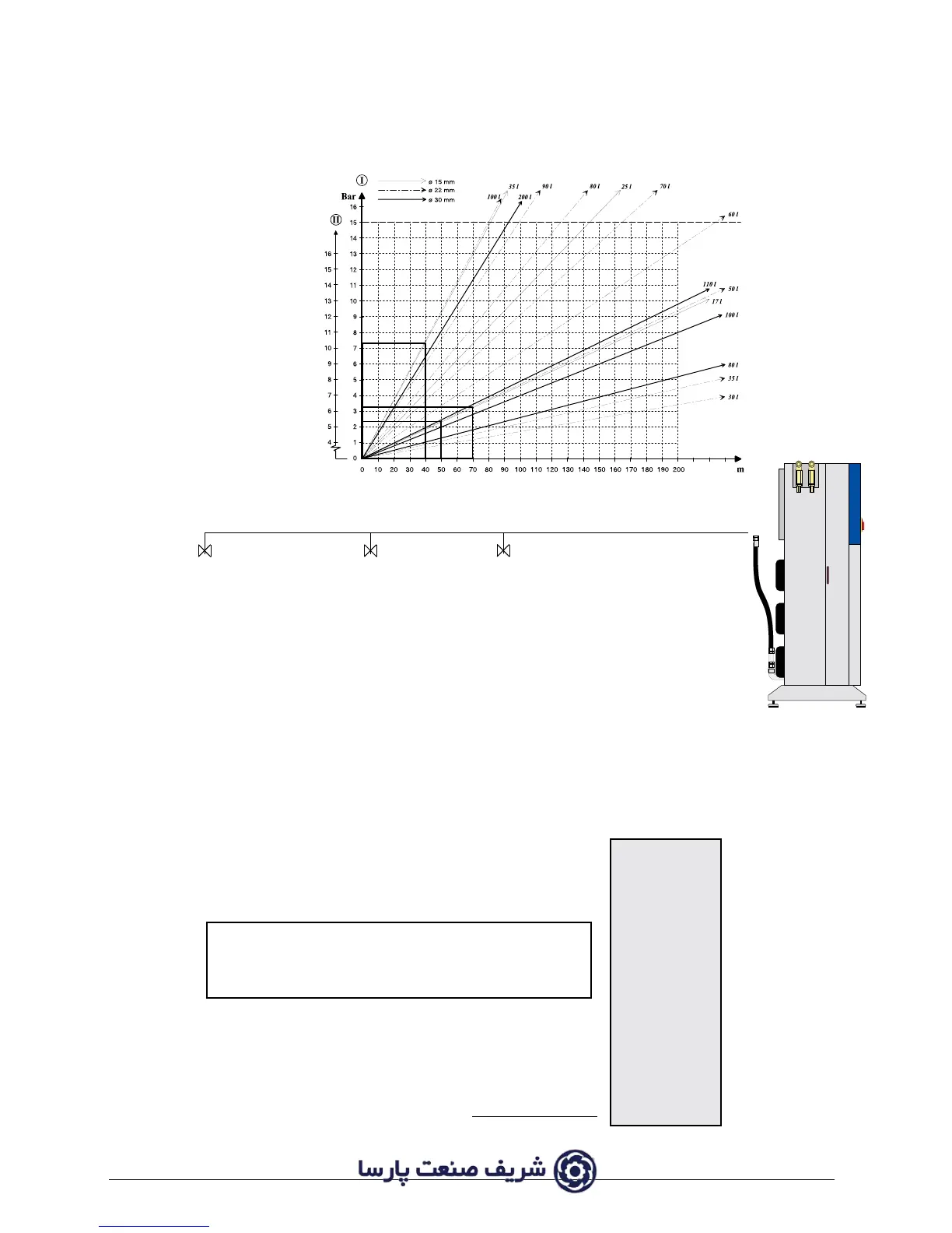
50 m
40 m
70 m
abc
M
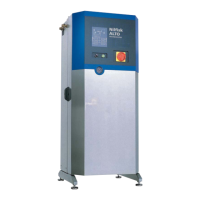
1.7.5 Examples
The following examples have been worked out on the basis of stainless steel pipes and a 160
bar system, and the dimension requirements are max.15 bar pressure drop from the machine
to the outlet points.
Example 1
Two different conditions may be used when
dimensioning the pipe system:
A. Based upon a fixed type of spray lance (capacity l/min)
B. Based upon max. capacity, i.e. all spray lances may be used anywhere
A:
If standard lances (17 l/min) are selected for outlet points a, b and c the maximum load on line
b-c = 17 l/min.
PRESSURE
According to the diagram the use of a 50 m ∅15 mm DROP
pipe will result in a pressure drop of: 2.3 bar
In the diagram you follow the 50 m division vertically
upwards to the curve symbolizing 17 l/min through an
∅15 mm pipe. From here proceed horizontally and a
pressure drop of 2.3 bar is had.
Maximum load on pipe line a-b = 35 l/min.
Use of 40 m Ø15 mm pipe will result in a pressure drop of: 7.4 bar
Maximum load on pipe line M-a = 51 l/min.
Use of 70 m Ø22 mm pipe will result in a pressure drop of: 3.3 bar
Total pressure drop 13.0 bar
The aggregate pressure drop on the three lines is less than 15 bar and the dimension requirements have therefore
been met.
 Loading...