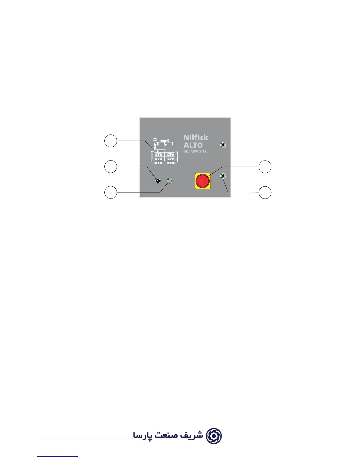
3.4 Instrument panel
The instrument panel is situated on the switchboard of the DELTABOOSTER.
1. Main / emergency switch (circuit breaker)
2. Operation switch - stopping switch
3. Starting switch
4. Switchboard
5. Locks for the door of the switchboard
3.4.1 Main / emergency switch
The main switch (1) connects the DELTABOOSTER to the supply network when the switch is
turned from pos. 0 to pos. I. At pos. 0 there is no connection between the DELTABOOSTER and
the supply network and the capacity of the switch is sufficient to use it as an emergency device.
The main switch may be locked in 0 position by means of an ordinary padlock. The switch should
always be locked during service checks of the system.
PLEASE NOTE: The switchboard can only be opened by means of a key and only when the
main switch (1) is in pos. 0.
3.4.2 Control switch / starting switch and stopping switch
The control switch (2) supplies 24VAC control voltage to the DELTABOOSTER when turned to
position I (provided the main switch is in pos. I).
The plant is started up by pressing the starting switch (3).
The plant will now be in operation / stand-by mode until the operation switch is turned back to
pos. 0.
Stop of plants in operation should always be effected on the operation switch and thus only use
the main / emergency switch for power cut off and emergencies.
 Loading...