OSEEX206-EN
8/10
INSTALLATION, OPERATION & MAINTENANCE INSTRUCTIONS
HANDLING & STORAGE
HANDLING
Proper care in handling the valve should be taken to
prevent damage. Do not drop or throw it.
STORAGE
Store the actuator in the protected area from dust,
moisture, and direct sunlight. If possible, actuator
should be kept in the original packaging.
CHECKING
• Check the product code, power supply, and voltage
before installation.
• Confirm that there is no screw loose or part
deformation.
• DIP switch be sure perform set up before a power
supply injection. Should not change an unnecessary
switch.
INSTALLATION
PRECAUTIONS
• Flush the pipeline carefully before installing the valve.
Foreign particles, such as sand or pieces of welding
electrode, will damage the ball and seats.
• Do not cut too much threading of the pipe to be
connected.
It deforms the valve and it causes leakage.
• If seal tape or sealant protrudes into the valve,
malfunction may result.
Pay attention to tape treatment and coating amount.
• EG / SH type has a flow direction. Install the valve
accordingly.
• Specify the SC option if a steam fluid. Flow direction is
restricted by SC option. (MS type)
• When the flow path is subjected to a high pressure
from arrow, it may leak slightly to the low pressure
port. (EL / TV / ST / SL)
E EG SR SH H EL TV ST SL type
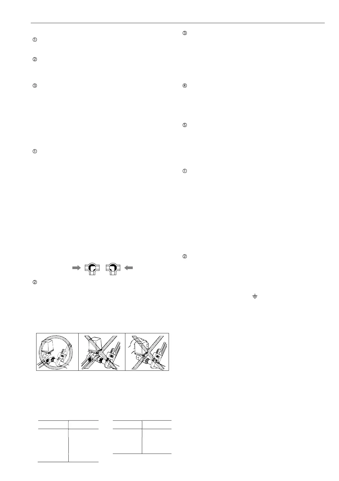
PIPING
• When piping, fix the end of the valve on the pipe side
with a smooth jaw wrench. (Fig. a)
• Do not place the wrench on the end of the valve
opposite the pipe to be connected. (Fig. b)
• Do not screw the valve into the pipe by holding the
actuator part with your hand. (Fig. c)
• Do not apply excessive force to the valve with a pipe
wrench or the like.
• When fixing the mounting posture,
please do not apply force in the loosening direction
(counterclockwise) of the coupling screw of the valve
body and cap.
Recommended torques [Nm]
Size [mm] Torque
008 to 010 15 to 25
015 25 to 35
020 40 to 50
025 50 to 60
Size [mm] Torque
032 60 to 80
040 75 to 85
050 90 to 110
ENVIRONMENT
• Do not install in place where corrosive gas is present
or where vibration is heavy (0.5 G or more).
• When radiant heat causes the surface temperature of
the control unit to exceed 50 °C, provide an
appropriate shielding plate.
• If there is a possibility that the fluid and drive part
freeze, please take measures to prevent freezing.
POSITIONING
• Should be positioned through 90° upward from
horizontal. Provide space around the product to allow
manual operation, inspection and replacement work.
• Maintenance space more than 105 mm upward from
the actuator is required.
OTHER NOTES
Until the wiring is completed there must be no
condensation or flooding in the interior of the actuator,
after piping. Protective caps on the cable gland are
not waterproof.
WIRING
PRECAUTIONS
• Remove the actuator cover before wiring.
• Two G1/2 electrical connections are provided with a
cable gland and plug. Usable cable size is 6 to 12
mm.
• When using a flexible tube, dew condensation may
occur inside the actuator due to respiration from the
inside of the tube and malfunction may result. Seal the
flexible tube connector part with a sealant.
• Sealants that affect the electrical contacts should not
be used inside the electric actuator.
• If long distance wiring or low voltage operation, check
that terminal voltage is in the proper range.
CONNECTION
• Do not wiring outdoors on a rainy day.
• Check the power supply and voltage.
Connect the signal as shown in the wiring diagram.
Do not connect unnecessarily terminal.
• Actuator should be electrically grounded.
Use the terminal marked ( ) inside the actuator.
PREVENT DEW CONDENSATION
• When installing the cover after wiring, perform the bolt
by the temporary tightening procedure and the
permanent tightening procedure to tightly and
securely tighten the rubber packing so that water does
not enter from the outside.
• Tighten the cable gland nut so that there is no leakage
from the wire entrance.
a b c
 Loading...