Do you have a question about the Nissei DG-503 and is the answer not in the manual?
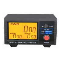
Indicates FWD/REF and VSWR readings for user reference.
Allows selection between HF and V/UHF frequency bands.
Controls the power on/off state of the device.
Enables DMR (TDMA)/AM/SSB measurement when rear switch is engaged.
Coaxial connector for connecting to the transmitter's RF output.
Coaxial connector for linking to the antenna system.
Connects to a 12V DC wire for device power.
Allows selection of DMR (TDMA), AM, SSB modes.
The NISSEI Digital SWR / Watt Meter, available in models DG-503 and DG-503MAX, is a highly accurate instrument designed for measuring Forward Power, Reflected Power, and the VSWR of both analog and digital transceivers. This device is an essential tool for radio enthusiasts and professionals who need to monitor the performance of their radio systems.
One of the primary functions of this meter is to provide precise measurements of forward and reflected power. Forward power refers to the power transmitted from the radio to the antenna, while reflected power is the power that bounces back from the antenna to the radio, often due to an impedance mismatch. By measuring these two values, the device helps users understand how efficiently their antenna system is radiating power. A high reflected power indicates a poor match, which can lead to reduced transmission efficiency and potential damage to the radio equipment.
In addition to power measurements, the meter also calculates and displays the Voltage Standing Wave Ratio (VSWR). VSWR is a critical parameter that indicates the impedance match between the transmitter and the antenna system. An ideal VSWR of 1:1 signifies a perfect match, meaning all power is being transmitted to the antenna without reflection. Higher VSWR values suggest a mismatch, which can cause power loss, signal distortion, and even damage to the transmitter's final amplifier stage. The ability to quickly and accurately determine VSWR allows users to tune their antenna systems for optimal performance and longevity.
The DG-503 and DG-503MAX models offer distinct capabilities regarding the types of transceivers they can measure. The DG-503 is designed for analog modes such as CW (Continuous Wave), FM (Frequency Modulation), and FDMA (Frequency Division Multiple Access). This makes it suitable for a wide range of traditional radio communications. The DG-503MAX, on the other hand, extends its functionality to include digital modes like DMR (Digital Mobile Radio), which uses TDMA (Time Division Multiple Access), as well as AM (Amplitude Modulation) and SSB (Single Sideband). This enhanced capability makes the DG-503MAX particularly versatile for modern radio systems that increasingly utilize digital communication protocols. The selection of these measurement modes is facilitated by a dedicated MAX switch located on the rear panel, allowing users to choose between standard analog measurements and advanced digital/AM/SSB measurements.
A key usage feature of these meters is their large 3.5-inch LCD display. This generous screen size ensures that readings for forward power, reflected power, and VSWR are clear and easy to read, even in varying lighting conditions. The display is also equipped with a backlight, further enhancing visibility and user convenience, especially in dimly lit environments. This thoughtful design element reduces eye strain and improves the overall user experience.
Operating the device is straightforward, thanks to its convenient control layout. A single push button allows users to cycle through the display of forward power, reflected power, and VSWR ratio, simplifying the process of monitoring these critical parameters. This intuitive interface means that users can quickly access the information they need without navigating complex menus or multiple controls.
The meters are designed for ease of integration into existing radio setups. They feature SO239 connectors (with an N-female option available), which are standard in many radio communication systems, ensuring compatibility with a wide range of transmitters and antennas. The input/output impedance is 50 Ohm, a common standard for RF equipment, further simplifying setup.
For power supply, the device requires a 12V DC source, and a 12V DC wire is included in the package. The power connection is clearly marked on the rear panel, with black indicating negative (-) and black/white indicating positive (+), preventing incorrect polarity connections.
Maintenance features are minimal, as the device is designed for reliable operation. The robust construction and high-quality components contribute to its durability. The insertion loss is less than 0.1 dB, indicating that the meter itself has a negligible impact on the signal path, preserving the integrity of the radio signal during measurements. This low insertion loss is crucial for accurate readings and efficient system performance.
The device comes packaged in a gift box, suggesting attention to presentation and protection during transit. The inclusion of an operation manual ensures that users have all the necessary information to set up and use the meter effectively.
In summary, the NISSEI Digital SWR / Watt Meter provides accurate and easy-to-read measurements of forward power, reflected power, and VSWR. Its user-friendly interface, large backlit LCD, and compatibility with both analog and, in the case of the DG-503MAX, digital communication modes make it a valuable tool for anyone involved in radio communication, from hobbyists to professionals. Its design prioritizes ease of use and reliable performance, contributing to optimal radio system operation and longevity.
| Frequency Range | 1.8-525MHz |
|---|---|
| Accuracy | ±5% |
| Impedance | 50Ω |
| Connectors | SO-239 |
| Weight | 540g |