SWR/POWER/MODULATION METE
R
Models : TM-3000/TM-2000 INSTRUCTION MANUAL
INTRODUCTION
TM-3000/2000 is a compact test meter to indicate the condition of 1.6-60 MHz / 26 -30 MHz antenna system
and transmitter with an impedance of 50 ohm. With TM series you can measure SWR, relative output power of the
transmitter and AM modulation.
SPECIFICATIONS
10W/30W/300W/3KW
(AVG) +/- 10% (AVG) +/- 10%
(AVG) +/- 5% (AVG) +/- 5%
POWER, SWR, MOD. POWER, SWR, MOD.
M type (SO-239) M type (SO-239)
190x85x135 (w/o holder) 190x85x135 (w/o holder)
800g (w/o holder) 800g (w/o holder)
Operation Manual Operation Manual
<FRONT PANEL>
<FRONT & REAR PANEL>
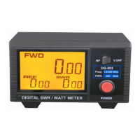
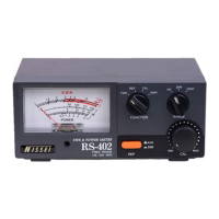
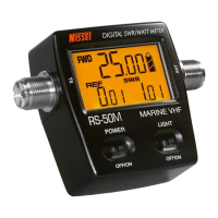
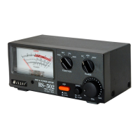
1. Meter Display : Indicates FWD/REV power and VSWR ratio, AM
Modulation.
2. Function switch : Selects FWD/REV power, VSWR, and Modulation
3. Range switch : Selects RF power range
4. Calibration control knob : Set full scale deflection when measuring
VSWR and AM modulation
5. AVG/PEP MONI. (elliptical push button) : Selects Average or PEP RF
Power readings
<REAR PANEL>
6. Meter Zero Adj. : Machnical zero adjustment for meter needle
7-
7. TX connector : Coax connector to transmitter 50 Ohm RF output.
8. ANT connector : Coax connector to 50 Ohm antenna system.
9. 13.8V DC connection for meter illumination.
10. Calibration MONI. (round push button) : Selects calibration or SWR
/MOD readings.
9- 8-
Minimum 1W
50 OHM
TM-2000
26 -30 MHz
0W - 1KW
10W/100W/1KW
1KW
MAX 100%
Testing Function
Input/Output Impedance
Input/Output Connectors
Dimension (W/H/D) mm
Weight (Net)
Accessories
3KW
MAX 100%
Minimum 1W
50 OHM
Power Scale
Maximum Power
AM Modulation
Accuracy 10W Range
30W - 3KW Range
SWR Measurement
Model TM-3000
1.6 - 60 MHz
0W - 3KW
Frequency Range
Power Range